Si5369-EVB Silicon Laboratories Inc, Si5369-EVB Datasheet
Si5369-EVB
Specifications of Si5369-EVB


Related parts for Si5369-EVB

Si5369-EVB Summary of contents
Page 1
... Si5365/66/67/68/ Introduction The Si5365/66-EVB,Si5367/68-EVB, and Si5369-EVB provide platforms for evaluating Silicon Laboratories' Si5365/Si5366, Si5367/Si5368, and Si5369 Any-Frequency Precision Clocks. The Si5365 and Si5366 are controlled directly using configuration pins on the devices, while the Si5367, Si5368, and Si5369 are controlled by a microprocessor or MCU (microcontroller unit) via an I clock multipliers with a loop bandwidth ranging from 30 kHz to 1 ...
Page 2
... For the MCU controlled devices (Si5367, Si5368, and Si5369)), the user also has the option of bypassing the MCU and controlling the parts from an external serial device. On-board termination is included so that the user can evaluate either single-ended or differential as well coupled clock inputs and outputs ...
Page 3
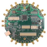
... CD with documentation and EVB software including the DSPLLsim configuration software utility USB cable EVB circuit board including a Si5366 (Si5365/66-EVB), a Si5368 (Si5367/68-EVB Si5369 (Si5369-EVB) User's Guide (this document) 4. Si5365/66-EVB, Si5367/68-EVB, and Si5369-EVB Quick Start 1. Install the Precision Clock EVB Driver. (This must be installed before the EVB is connected to the PC via the USB cable.) For details, see Section " ...
Page 4
... Functional Description The Si5365/66-EVB, Si5367/68-EVB, Si5369-EVB, and DSPLLsim software allow for a complete and simple evaluation of the functions, features, and performance of the Si536x Any-Frequency Precision Clocks. 5.1. Narrowband versus Wideband Operation This document describes three evaluation boards: one for the Si5365 and Si5366, another for the Si5367 and Si5368, and a third for the Si5369 ...
Page 5
... The Si5366, Si5368, and Si5369 require that an external reference clock be provided to enable the devices to operate as narrowband jitter attenuators with loop bandwidths as low (as low for the Si5369). The external reference clock can be either a crystal, a stand-alone oscillator or some other clock source. The range of acceptable reference frequencies is described in the Any-Frequency Precision Clocks Family Reference Manual (Si53xx-RM) ...
Page 6
5.4. CPLD This CPLD ...
Page 7
Power and 2L Signals This evaluation board requires two power inputs +3.3 V for the MCU and either 1.8, 2.5, or 3.3 V for the Any- Frequency Precision Clock part. The power connector is J40. The grounds for the ...
Page 8
Connectors and LEDs ...
Page 9
User Jumpers and Headers. Use Figure 4 to locate the jumpers described in Tables and 7: J14 J14 J17 J17 J22 J22 Figure 4. Connectors, Jumper Header Locations J25 assists in measuring the Any-Frequency Precision Clock ...
Page 10
J14 is a three-pin ...
Page 11
Table 6. External Serial Port Connector, J22 J17 is a three-pin by twenty header that is used to establish input levels for the pin controlled three-level inputs using jumper plugs. It also provides a means of externally driving the three-level ...
Page 12
EVB Software Installation ...
Page 13
Precision Clock EVB Software Installation To install: 1. Navigate to the "PrecisionClockEVBSoftware" directory. 2. Double-click on the Setup.exe file 3. Follow the steps in the wizard to install the program. Note: Use the default installation location for best results. ...
Page 14
Schematics 3 3 ...
Page 15
Rev. 0 ...
Page 16
Gnd1 2 NC2 3 ...
Page 17
Rev. 0 ...
Page 18
...
Page 19
Bill of Materials Item Qty Reference 1 32 C1,C2,C3,C5,C10,C12,C17,C19,C21 ,C25,C26,C27,C28,C29,C32,C33,C3 6,C37,C38,C40,C42,C44,C45,C47,C 49,C50,C53,C55,C57,C58,C60,C61 2 7 C4,C6,C8,C9,C14,C23,C52 3 3 C7,C30,C31 4 16 C11,C13,C15,C16,C18,C20,C24,C41 ,C43,C46,C48,C51,C54,C56,C59, C34,C35 7 6 D1,D3,D10,D12,D14,D16 8 8 D2,D4,D5,D6,D8,D11,D13,D15 9 2 D7, H1,H2,H3,H4 11 ...
Page 20
... R18,R20,R30,R50,R62,R64 38 1 R43 41 1 R51 *Note: X denotes the product revision. Consult the ordering guide in the Si5368 Data Sheet for the latest product revision. For the Si5365/66-EVB, substitute Si5366-C-GQ. For the Si5369-EVB, substitute Si5369A-C-GQ. 20 Part Mfgr 10 Venkel 0 ohm Venkel 66.5 Venkel ...
Page 21
Layout Figure 10. Silkscreen Top Figure 11. Layer 1 Rev. 0 ...
Page 22
Figure 12. Layer ...
Page 23
Figure 14. Layer 4, 3.3 V Power Figure 15. Layer 5 Rev. 0 ...
Page 24
Figure 16. Layer ...
Page 25
Figure 18. Layer 8 Figure 19. Silkscreen Bottom Rev. 0 ...
Page 26
... MHz output on CKOUT1 and CKOUT2 622.08 MHz output on CKOUT3 and CKOUT4 311.04 MHz output on CKOUT5 Loop for the Si5367/68-EVB for the Si5369-EVB LVEPCL outputs for CKIN1, CKIN2, CKIN3 and CKIN4 For the Si5365/66-EVB, the factory jumper settings are as follows: For J17: ...
Page 27
For J14: Pin Pin Jumper CS0_C3A J14.1B none CS1_C4A J14.2B none INC J14.3B none DEC J14.4B none — J14.5B none — J14.6B none DBL34 J14.7B none FS_ALIGN J14.8B none FS_SW J14.9B none CK_CONF J14.10B none ...
Page 28
... Settings" on page 26. Revision 0.3 to Revision 0.4 Updated for free run mode. Revision 0.4 to Revision 0.5 Added warning about low clock input frequencies to section "5.3.Si536x Input and Output Clocks" on page 5. Changed any-rate to any-frequency. Added the Si5369-EVB. 28 Rev. 0.5 ...
Page 29
N : OTES Rev. 0 ...
Page 30
... Should Buyer purchase or use Silicon Laboratories products for any such unintended or unauthorized ap- plication, Buyer shall indemnify and hold Silicon Laboratories harmless against all claims and damages. Silicon Laboratories, Silicon Labs, and DSPLL are trademarks of Silicon Laboratories Inc. Other products or brandnames mentioned herein are trademarks or registered trademarks of their respective holders. ...