STA310 STMicroelectronics, STA310 Datasheet - Page 12

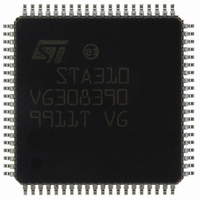
STA310
Manufacturer Part Number
STA310
Description
IC AUDIO DECODER 6+2CH 80-TQFP
Manufacturer
STMicroelectronics
Type
Audio Decoderr
Datasheet
1.STA310.pdf
(90 pages)
Specifications of STA310
Applications
HDTV, Players, Receivers, Set-Top Boxes
Voltage - Supply, Analog
2.5V
Voltage - Supply, Digital
2.5V
Mounting Type
Surface Mount
Package / Case
80-TQFP, 80-VQFP
Audio Codec Type
MP3 Decoder
No. Of Dacs
3
No. Of Input Channels
2
No. Of Output Channels
6
Adc / Dac Resolution
32bit
Sampling Rate
192kHz
Interface Type
I2C, Serial, Parallel
Rohs Compliant
Yes
Lead Free Status / RoHS Status
Lead free / RoHS Compliant
Other names
497-8856
STA310
STA310
Available stocks
Company
Part Number
Manufacturer
Quantity
Price
Part Number:
STA310
Manufacturer:
ST
Quantity:
20 000
STA310
4.2.1 System clock
The system clock sent to the DSP core and the peripherals can be derived from 4 sources and the selection is
performed through an Host Register; external clock, external clock divided by 2, internal system PLL and inter-
nal system PLL divided by 2.
The system PLL is used to create the system clock from the input clock. This PLL is software programmable
through the Host Registers mechanism. The system PLL is used to set the any frequency up to the maximum
allowed device speed. After hard reset the system clock is running at 47.25MHz. An RC network must be con-
nected to the filter Pin PLLSF.
The system clock is output on the pin CLKOUT after a programmable divider ranging from 1 to 16.
4.2.2 DAC clocks
4.2.2.1 PCM clock
The PCM clock can be either input to the device or generated by the internal PLL or recovered by the embedded
SPDIF receiver. The selection is done via the Host Registers.
After a hardware reset, the internal PLL is disabled and the PCMCLK pad is an input. PCMCLK may be equal
to the PCM output bit rate, or it may be an integer multiple of this, allowing the use of oversampling D-A con-
verters.
The internal fractional PLL is able to generate PCMCLK at any “FsX Oversampling Factor” frequencies, where
Fs is any multiple or sub-multiple of the two 44.1kHz and 48kHz sampling frequencies. An RC network must be
connected to the filter pin PLLAF; refer to External circuitry on page 9 for recommended values.
If the PCMCLK is recovered from the embedded SPDIF receiver, the only supported overampling frquency is
128 Fs.
4.2.2.2 Bit clock SCLK
The PCM serial clock SCLK is the bit clock. It provides clocks for each time slot (16 cycles for each channel in
16-bit mode, 32 cycles for each channel in 18-, 20-, 24-bit modes). The frequency of SCLK is therefore fixed to
2 x Nb time slots x Fs, where Fs is the sample frequency.
The clock is derived from the clock PCMCLK. The register PCMDIVIDER must be configured according to the
selected output precision and the frequency of PCMCLK, so that the device can construct SCLK:
Fsclk = Fpcmclk / (2 x (PCMDIVIDER+1)) gives
Table 1.
The value of PCMDIVIDER = 0 is reserved. If this number is loaded, the divider is bypassed and the frequency
of SCLK equals the frequency of PCMCLK. The PCMDIVIDER register must be setup before the output of SCLK
starts.
This can be done by first disabling PCM outputs, by de-asserting the MUTE and PLAY commands and then
writing into the PCMDIVIDER register. Once the register is setup, the MUTE and/or PLAY commands can be
asserted. PCMDIVIDER can not be changed “on the fly”.
12/90
5
3
2
1
PCM Divider Value
PCMCLK = 384 Fs, DAC is 16-bit mode
PCMLK = 256 Fs, DAC is 16-bit mode
PCMLK = 384 Fs, DAC is 32-bit mode
PCMLK = 256 Fs, DAC is 32-bit mode
Mode Description


