HMP8117CNZ Intersil, HMP8117CNZ Datasheet - Page 45
HMP8117CNZ
Manufacturer Part Number
HMP8117CNZ
Description
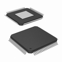
IC VIDEO DECODER NTSC/PAL 80PQFP
Manufacturer
Intersil
Type
Video Decoderr
Datasheet
1.HMP8117CNZ.pdf
(45 pages)
Specifications of HMP8117CNZ
Applications
Video
Voltage - Supply, Analog
4.75 V ~ 5.25 V
Voltage - Supply, Digital
4.75 V ~ 5.25 V
Mounting Type
Surface Mount
Package / Case
80-MQFP, 80-PQFP
Lead Free Status / RoHS Status
Lead free / RoHS Compliant
Available stocks
Company
Part Number
Manufacturer
Quantity
Price


Metric Plastic Quad Flatpack Packages (MQFP)
Intersil products are sold by description only. Intersil Corporation reserves the right to make changes in circuit design, software and/or specifications at any time without
notice. Accordingly, the reader is cautioned to verify that data sheets are current before placing orders. Information furnished by Intersil is believed to be accurate and
reliable. However, no responsibility is assumed by Intersil or its subsidiaries for its use; nor for any infringements of patents or other rights of third parties which may result
from its use. No license is granted by implication or otherwise under any patent or patent rights of Intersil or its subsidiaries.
E E1
0.016 MIN
0.40
0
0
o
o
-7
-H-
MIN
o
-A-
L
PIN 1
All Intersil U.S. products are manufactured, assembled and tested utilizing ISO9000 quality systems.
Intersil Corporation’s quality certifications can be viewed at www.intersil.com/design/quality
12
12
o
o
For information regarding Intersil Corporation and its products, see www.intersil.com
-16
-16
A2 A1
o
o
45
D1
D
0.008
0.20
-D-
0.005/0.007
BASE METAL
0.13/0.17
WITH PLATING
M
C
A-B
S
0.005/0.009
A
b1
D
0.13/0.23
b
-B-
S
-C-
SEATING
e
PLANE
0.076
0.003
HMP8117
Q80.14x20
80 LEAD METRIC PLASTIC QUAD FLATPACK PACKAGE
NOTES:
SYMBOL
1. Controlling dimension: MILLIMETER. Converted inch
2. All dimensions and tolerances per ANSI Y14.5M-1982.
3. Dimensions D and E to be determined at seating plane
4. Dimensions D1 and E1 to be determined at datum plane
5. Dimensions D1 and E1 do not include mold protrusion.
6. Dimension b does not include dambar protrusion. Allowable
7. “N” is the number of terminal positions.
ND
NE
A1
A2
D1
E1
b1
dimensions are not necessarily exact.
Allowable protrusion is 0.25mm (0.010 inch) per side.
dambar protrusion shall be 0.08mm (0.003 inch) total.
D
N
A
E
b
L
e
-H-
.
0.010
0.098
0.012
0.012
0.908
0.782
0.673
0.547
0.029
MIN
-
(JEDEC MS-022GB-1 ISSUE B)
0.032 BSC
INCHES
80
24
16
MAX
0.134
0.114
0.018
0.016
0.918
0.792
0.681
0.555
0.040
-
23.08
19.88
17.10
13.90
0.25
2.50
0.30
0.30
0.73
MILLIMETERS
MIN
-
0.80 BSC
80
24
16
23.32
20.12
17.30
14.10
MAX
3.40
2.90
0.45
0.40
1.03
-
Rev. 1 4/99
NOTES
4, 5
4, 5
6
3
3
7
-
-
-
-
-
-
-
-
-C-
.
Related parts for HMP8117CNZ
Image
Part Number
Description
Manufacturer
Datasheet
Request
R

Part Number:
Description:
Ntsc/pal Video Decoder
Manufacturer:
Intersil Corporation
Datasheet:
Part Number:
Description:
Intersil Corporation [CMOS Serial Controller Interface]
Manufacturer:
Intersil Corporation
Datasheet:
Part Number:
Description:
Manufacturer:
Intersil Corporation
Datasheet:
Part Number:
Description:
357-036-542-201 CARDEDGE 36POS DL .156 BLK LOPRO
Manufacturer:
Intersil Corporation
Datasheet:
Part Number:
Description:
1024-Word x 4-Bit LSI Static RAM
Manufacturer:
Intersil Corporation
Datasheet:
Part Number:
Description:
General Purpose NPN Transistor Arrays FN341.4
Manufacturer:
Intersil Corporation
Datasheet:
Part Number:
Description:
CMOS 16-Bit Microprocessor
Manufacturer:
Intersil Corporation
Datasheet:
Part Number:
Description:
Manufacturer:
Intersil Corporation
Datasheet:
Part Number:
Description:
Manufacturer:
Intersil Corporation
Datasheet:
Part Number:
Description:
Manufacturer:
Intersil Corporation
Datasheet:
Part Number:
Description:
Manufacturer:
Intersil Corporation
Datasheet:
Part Number:
Description:
CMOS 6-Bit Latch and Decoder Memory Interfaces
Manufacturer:
Intersil Corporation
Datasheet:
Part Number:
Description:
CA3046General Purpose NPN Transistor Arrays
Manufacturer:
Intersil Corporation
Datasheet:
Part Number:
Description:
Manufacturer:
Intersil Corporation
Datasheet:
Part Number:
Description:
TR909 DLC/FLC SLIC with Low Power Standby
Manufacturer:
Intersil Corporation
Datasheet: