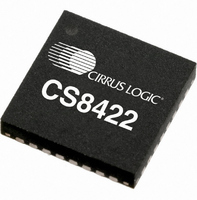
CS8422-CNZ Cirrus Logic Inc, CS8422-CNZ Datasheet - Page 39

CS8422-CNZ
Manufacturer Part Number
CS8422-CNZ
Description
IC SAMPLE RATE CONVERTER 32QFN
Manufacturer
Cirrus Logic Inc
Type
Sample Rate Converterr
Datasheet
1.CS8422-CNZ.pdf
(82 pages)
Specifications of CS8422-CNZ
Package / Case
32-QFN
Applications
Digital Audio
Mounting Type
Surface Mount
Maximum Operating Temperature
+ 125 C
Minimum Operating Temperature
- 55 C
Mounting Style
SMD/SMT
Package
32QFN
Operating Temperature
-55 to 125 °C
Audio Control Type
Sample Rate Converter
Control Interface
I2C, SPI
Supply Voltage Range
1.71V To 5.25V
Operating Temperature Range
-40°C To +85°C
Audio Ic Case Style
QFN
No. Of Pins
32
Rohs Compliant
Yes
Lead Free Status / RoHS Status
Lead free / RoHS Compliant
For Use With
598-1568 - BOARD EVAL FOR CS8422 RCVR
Lead Free Status / Rohs Status
Lead free / RoHS Compliant
Other names
598-1732
Available stocks
Company
Part Number
Manufacturer
Quantity
Price
Company:
Part Number:
CS8422-CNZ
Manufacturer:
CIRRUS
Quantity:
99
Part Number:
CS8422-CNZ
Manufacturer:
CIRRUS
Quantity:
20 000
Part Number:
CS8422-CNZR
Manufacturer:
CIRRUS
Quantity:
20 000
DS692F1
7.4.1
7.4.2
8. HARDWARE MODE CONTROL
The CS8422 provides a stand-alone hardware control mode in which the part does not require an I²C or SPI control
port. In Hardware Mode, the user is provided with a subset of the features available in Software Mode as shown in
Figure
VL upon the release of RST.
Controlling the CS8422 in Hardware Mode is done through dedicated control inputs, 20 k pull-up or pull-down re-
sistors attached to dual-purpose pins, and by attaching a specific resistor values from one of two dedicated control
pins (SAOF and MS_SEL) to either VL or ground. In the case of SAOF and MS_SEL, the resistor should be con-
nected as close to the pin as possible and should have a tolerance no greater than ±1%. Dedicated controls
(TX_SEL and RX_SEL) can be changed during operation whereas pull-up resistor controls are sensed on startup.
Figure 21
scribed in the table below.
RXP/RXN0
RXP/RXN1
21. The part will be in Hardware Mode if there is a 20 k pull-up resistor connected between the C pin and
Hardware Mode Control
In Hardware Mode, the default master clock source for the SRC is the internal ring oscillator. Therefore,
it is not necessary to apply an external MCLK source for the SRC. Optionally the user may select the PLL
clock as the SRC MCLK source by connecting a 20 k pull-up resistor between MCLK_OUT and VL.
Software Mode Control
In Software Mode, the SRC master clock source is selected by the SRC_MCLK[1:0] bits in the
put Serial Port Clock Control (08h)”
to VL or DGND and XTO is left unconnected, then the internal ring oscillator will take the place of the XTI-
XTO clock source.
If the selected SRC MCLK source is XTI-XTO, and is greater that 33 MHz, the user can enable the internal
clock divide-by-two by setting the SRC_DIV bit in control port register 08h. See
Clock Control (08h)” on page 51
shows clock routing options available in Hardware Mode. Control signal names are in italics and are de-
2
2
MUX
MUX
2:1
2:1
RX_SEL
TX_SEL
Figure 21. Hardware Mode Clock Routing
(MCLK_OUT Pull-up)
Ring Oscillator
Recovery
Receiver
Clock
(PLL)
for more details.
register. If the XTI clock is selected as the SRC MCLK and XTI is tied
M UX
2:1
Converter
Sam ple
Rate
(RMCK Pull-Up)
Generator
XTI XTO
Clock
M UX
2:1
MS_SEL
MS_SEL
SAOF
SAOF
Output
Output
Audio
Audio
Serial
Serial
1
2
“SRC Output Serial Port
CS8422
“SRC Out-
TX
TDM _IN1
SDOUT1
OSCLK1
OLRCK1
SDOUT2
OSCLK2
OLRCK2
MCLK_OUT
RM CK
39


