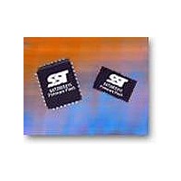
SST49LF016C-33-4C-WHE Microchip Technology, SST49LF016C-33-4C-WHE Datasheet - Page 17

SST49LF016C-33-4C-WHE
Manufacturer Part Number
SST49LF016C-33-4C-WHE
Description
IC FLASH SER LPC 16MBIT 32TSOP
Manufacturer
Microchip Technology
Datasheets
1.SST49LF080A-33-4C-NHE.pdf
(2 pages)
2.SST49LF080A-33-4C-NHE.pdf
(2 pages)
3.SST49LF016C-33-4C-NHE.pdf
(36 pages)
Specifications of SST49LF016C-33-4C-WHE
Memory Type
FLASH
Memory Size
16M (2M x 8)
Operating Temperature
0°C ~ 85°C
Package / Case
32-TSOP
Format - Memory
FLASH
Speed
33MHz
Interface
Parallel
Voltage - Supply
3 V ~ 3.6 V
Data Bus Width
8 bit
Architecture
Sectored
Interface Type
Parallel, Serial
Supply Voltage (max)
3.6 V
Supply Voltage (min)
3 V
Maximum Operating Current
18 mA
Mounting Style
SMD/SMT
Organization
4 KB x 512
Lead Free Status / RoHS Status
Lead free / RoHS Compliant
Lead Free Status / RoHS Status
Lead free / RoHS Compliant, Lead free / RoHS Compliant
Available stocks
Company
Part Number
Manufacturer
Quantity
Price
Company:
Part Number:
SST49LF016C-33-4C-WHE
Manufacturer:
Microchip Technology
Quantity:
135
16 Mbit LPC Serial Flash
SST49LF016C
Program-Suspend/
Program-Resume Command
The Program-Suspend and Program-Resume commands
have no influence on the device. Since the device requires
a maximum of T
Table 26), when a Program-Suspend command is written,
the suspended Byte Program operation will always be suc-
cessfully completed within the suspend latency time (T
T
Security ID Commands
The SST49LF016C device offers a 256-bit Security ID
space. The Security ID space is divided into two parts. One
64-bit segment is programmed at SST with a unique 64-bit
number: this number cannot be changed by the user. The
other segment is 192-bit wide and is left blank: this space is
available for customers and can be programmed as
desired.
The User-Security-ID-Program command is shown in
Table 8, “Software Command Sequence”. Use the memory
addresses specified in Table 11 for Security ID program-
ming. Once the customer segment is programmed, it can
be locked to prevent any alteration. The User-Security-ID-
Program-Lockout command is shown in Table 8, “Software
Command Sequence”.
In order to read the Security ID information, the user can
issue a Read Security ID Command (90H) to the device. At
this point the device enters the Read-Software-ID/Read-
Security-ID mode. The Security ID information can be read
at the memory addresses in Table 11.
A Read-Array/Reset command (FFH) must then be issued
to the device in order to exit the Read-Software-ID/Read-
Security-ID mode and return to Read-Array mode.
An alternate method to read the Security ID information is
to read the Security ID registers located into the register
space as described in the “Security ID Registers” section.
TABLE 11: Security ID Addresses
©2008 Silicon Storage Technology, Inc.
BP
FIGURE 8: Erase-Suspend Flow Chart
= 10 µs).
FFFC 0180 to FFFC 0187
FFFC 0188 to FFFC 019F
Address Range
BP
(10 µs) in order to program a byte (see
Security ID Segment
Factory-Programmed
User-Programmed
ES
=
17
device memory address
device memory address
device memory address
command to read from
Write D0H to any valid
Write B0H to any valid
Write 70H to any valid
command to program
Write the Read-Array
Read Status Register
another Sector/Block
another Sector/Block
Erase Sector/Block
Write the Program
Erase Resumed
WSMS = 1
Finished?
ESS = 1
or
Yes
Yes
Yes
No
24 bytes – 192 bit
8 bytes – 64 bit
No
No
Size
Read-Status-Register
Erase Completed
1237 FC_Erase-Sus.1
Erase-Suspend
Erase-Resume
S71237-08-000
Command
Command
Command
Data Sheet
T11.0 1237
5/08


