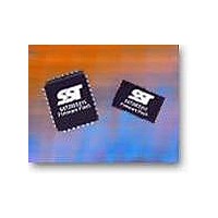
SST49LF016C-33-4C-WHE Microchip Technology, SST49LF016C-33-4C-WHE Datasheet - Page 20

SST49LF016C-33-4C-WHE
Manufacturer Part Number
SST49LF016C-33-4C-WHE
Description
IC FLASH SER LPC 16MBIT 32TSOP
Manufacturer
Microchip Technology
Datasheets
1.SST49LF080A-33-4C-NHE.pdf
(2 pages)
2.SST49LF080A-33-4C-NHE.pdf
(2 pages)
3.SST49LF016C-33-4C-NHE.pdf
(36 pages)
Specifications of SST49LF016C-33-4C-WHE
Memory Type
FLASH
Memory Size
16M (2M x 8)
Operating Temperature
0°C ~ 85°C
Package / Case
32-TSOP
Format - Memory
FLASH
Speed
33MHz
Interface
Parallel
Voltage - Supply
3 V ~ 3.6 V
Data Bus Width
8 bit
Architecture
Sectored
Interface Type
Parallel, Serial
Supply Voltage (max)
3.6 V
Supply Voltage (min)
3 V
Maximum Operating Current
18 mA
Mounting Style
SMD/SMT
Organization
4 KB x 512
Lead Free Status / RoHS Status
Lead free / RoHS Compliant
Lead Free Status / RoHS Status
Lead free / RoHS Compliant, Lead free / RoHS Compliant
Available stocks
Company
Part Number
Manufacturer
Quantity
Price
Company:
Part Number:
SST49LF016C-33-4C-WHE
Manufacturer:
Microchip Technology
Quantity:
135
Data Sheet
TABLE 15: Block Locking Register Bits
Write-Lock Bit
The Write-Lock bit, bit 0, controls the lock state described
in Table 15. The default Write status of all blocks after
power up is write locked. When bit 0 of the Block Locking
register is set, Program and Erase operations for the corre-
sponding block are prevented. Clearing the Write-Lock bit
will unprotect the block. The Write-Lock bit must be cleared
prior to starting a Program or Erase operation since it is
sampled at the beginning of the operation. The Write-Lock
bit functions in conjunction with the hardware Write Lock
pin TBL# for the top Boot Block. When TBL# is low, it over-
rides the software locking scheme. The top Boot Block
Locking register does not indicate the state of the TBL#
pin. The Write-Lock bit functions in conjunction with the
hardware WP#/AAI pin for the remaining blocks (Blocks 0
to 33 for 49LF016C). When WP#/AAI is low, it overrides
the software locking scheme. The Block Locking register
does not indicate the state of the WP#/AAI pin.
©2008 Silicon Storage Technology, Inc.
Reserved Bit
[7:3]
00000
00000
00000
00000
00000
00000
00000
00000
Read-Lock Bit
[2]
0
0
0
0
1
1
1
1
Lock-Down Bit
[1]
0
0
1
1
0
0
1
1
Write-Lock Bit
[0]
0
1
0
1
0
1
0
1
20
Lock-Down Bit
The Lock-Down bit, bit 1, controls the Block Locking regis-
ter as described in Table 15. When in LPC interface mode,
the default Lock Down status of all blocks upon power-up is
not locked down. Once the Lock-Down bit is set, any future
attempted changes to that Block Locking register will be
ignored. The Lock-Down bit is only cleared upon a device
reset with RST# or INIT# or power down. Current Lock
Down status of a particular block can be determined by
reading the corresponding Lock-Down bit. Once a block’s
Lock-Down bit is set, the Read-Lock and Write-Lock bits for
that block can no longer be modified: the block is locked
down in its current state of read/write accessibility.
Read-Lock Bit
The default read status of all blocks upon power-up is read-
unlocked. When a block’s read lock bit is set, data cannot
be read from that block. An attempted read from a read-
locked block will result in the data 00h. The read lock status
can be unlocked by clearing the read lock bit: this can only
be done provided that the block is not locked down. The
current read lock status of a particular block can be deter-
mined by reading the corresponding read-lock bit.
Lock Status
Full Access
Write Locked (Default State at Power-Up)
Locked Open (Full Access Locked Down)
Write Locked Down
Block Read Locked (Registers alterable)
Block Read & Write Lock (Registers alterable)
Block Read Locked Down (Registers not alterable)
Block Read & Write lock Down (Registers not alterable)
16 Mbit LPC Serial Flash
SST49LF016C
S71237-08-000
T15.0 1237
5/08


