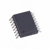
EPCS16SI16N Altera, EPCS16SI16N Datasheet - Page 27

EPCS16SI16N
Manufacturer Part Number
EPCS16SI16N
Description
IC CONFIG DEVICE 16MBIT 16-SOIC
Manufacturer
Altera
Series
EPCSr
Specifications of EPCS16SI16N
Programmable Type
In System Programmable
Memory Size
16Mb
Voltage - Supply
3 V ~ 3.6 V
Operating Temperature
-40°C ~ 85°C
Package / Case
16-SOIC (0.300", 7.50mm Width)
Memory Type
Flash
Clock Frequency
20MHz
Supply Voltage Range
2.7V To 3.6V
Memory Case Style
SOIC
No. Of Pins
16
Operating Temperature Range
-40°C To +85°C
Rohs Compliant
Yes
Lead Free Status / RoHS Status
Lead free / RoHS Compliant
Other names
544-1240-5
EPCS16SI16
EPCS16SI16
Available stocks
Company
Part Number
Manufacturer
Quantity
Price
Company:
Part Number:
EPCS16SI16N
Manufacturer:
ALTERA
Quantity:
1 250
Company:
Part Number:
EPCS16SI16N
Manufacturer:
ALTERA44
Quantity:
540
Part Number:
EPCS16SI16N
Manufacturer:
ALTERA/阿尔特拉
Quantity:
20 000
Chapter 3: Serial Configuration Devices (EPCS1, EPCS4, EPCS16, EPCS64, and EPCS128) Data Sheet
Timing Information
Timing Information
Figure 3–18. Write Operation Timing
Table 3–16. Write Operation Parameters (Part 1 of 2)
June 2011 Altera Corporation
f
t
t
t
WCLK
CH
CL
NCSSU
Symbol
Power-On Reset
Error Detection
f
Write clock frequency (from FPGA, download cable, or
embedded processor) for write enable, write disable,
read status, read silicon ID, write bytes, erase bulk, and
erase sector operations
DCLK high time
DCLK low time
Chip select (nCS) setup time
During initial power-up, a POR delay occurs to ensure the system voltage levels have
stabilized. During AS configuration, the FPGA controls the configuration and has a
longer POR delay than the serial configuration device.
For the POR delay time, refer to the configuration chapter in the appropriate device
handbook.
During AS configuration with the serial configuration device, the FPGA monitors the
configuration status through the nSTATUS and CONF_DONE pins. If an error condition
occurs (nSTATUS drives low) or if the CONF_DONE pin does not go high, the FPGA will
begin reconfiguration by pulsing the nSTATUS and nCSO signals, which controls the
chip select pin on the serial configuration device (nCS).
After an error, configuration automatically restarts if the Auto-Restart Upon Frame
Error option is turned on in the Quartus
system must monitor the nSTATUS signal for errors and then pulse the nCONFIG signal
low to restart configuration.
Figure 3–18
device.
Table 3–16
operation.
DCLK
DATA
ASDI
nCS
t
NCSH
High Impedance
defines the serial configuration device timing parameters for write
t
DSU
shows the timing waveform for write operation to the serial configuration
Parameter
Bit n
t
NCSSU
t
DH
Bit n 1
t
CH
t
®
CL
II software. If the option is turned off, the
Bit 0
Min
—
20
20
10
t
CSH
Typ
—
—
—
—
Volume 2: Configuration Handbook
Max
—
25
—
—
MHz
Unit
ns
ns
ns
3–27


