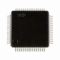
PCF8578H/1,118 NXP Semiconductors, PCF8578H/1,118 Datasheet - Page 8

PCF8578H/1,118
Manufacturer Part Number
PCF8578H/1,118
Description
IC LCD DRIVER DOT MATRIX 64-LQFP
Manufacturer
NXP Semiconductors
Datasheet
1.PCF8578H1118.pdf
(46 pages)
Specifications of PCF8578H/1,118
Display Type
LCD
Configuration
Dot Matrix
Interface
I²C
Voltage - Supply
2.5 V ~ 6 V
Operating Temperature
-40°C ~ 85°C
Mounting Type
Surface Mount
Package / Case
64-LQFP
Lead Free Status / RoHS Status
Lead free / RoHS Compliant
Current - Supply
-
Digits Or Characters
-
Lead Free Status / Rohs Status
Details
Other names
935276284118
PCF8578H/1-T
PCF8578H/1-T
PCF8578H/1-T
PCF8578H/1-T
Available stocks
Company
Part Number
Manufacturer
Quantity
Price
Company:
Part Number:
PCF8578H/1,118
Manufacturer:
NXP Semiconductors
Quantity:
10 000
NXP Semiconductors
8. Functional description
PCF8578_6
Product data sheet
8.1 Display configurations
The PCF8578 row and column driver is designed for use in one of three ways:
Table 4.
[1]
[2]
In mixed mode, the device functions as both a row and column driver. It can be used in
small stand-alone applications, or for larger displays with up to 15 PCF8579s
(31 PCF8579s when two slave addresses are used). See
configurations.
In row mode, the device functions as a row driver with up to 32 row outputs and provides
the clock and synchronization signals for the PCF8579. Up to 16 PCF8579s can normally
be cascaded (32 when two slave addresses are used).
Timing signals are derived from the on-chip oscillator, whose frequency is determined by
the value of the resistor connected between pin OSC and pin V
Five commands are available to configure and control the operation of the device.
Communication is made via a two-line bidirectional I
two slave addresses. The only difference between these slave addresses is the least
significant bit, which is set by the logic level applied to SA0. The PCF8578 and PCF8579
have different subaddresses. The subaddress of the PCF8578 is only defined in mixed
mode and is fixed at 0111 100 (see
accessed in mixed mode and data is loaded as described for the PCF8579.
Bias levels may be generated by an external potential divider with appropriate decoupling
capacitors. For large displays, bias sources with high drive capability should be used. A
typical mixed mode system operating with up to 15 PCF8579s is shown in
stand-alone system would be identical but without the PCF8579).
Applicatio
n
stand alone 1:8
with
PCF8579
•
•
•
Stand-alone row and column driver for small displays (mixed mode)
Row and column driver with cascaded PCF8579s (mixed mode)
Row driver with cascaded PCF8579s (mixed mode and row mode)
Using 15 PCF8579s.
Using 16 PCF8579s.
Possible display configurations
Multiplex rate Mixed mode
1:16
1:24
1:32
1:8
1:16
1:24
1:32
Rev. 06 — 5 May 2009
Rows
16
24
32
8
16
24
32
8
[1]
[1]
[1]
[1]
LCD row/column driver for dot matrix graphic displays
Section 8.8.7 on page
Columns Rows
32
24
16
632
624
616
608
8
[1]
[1]
[1]
[1]
Row mode
-
-
-
-
8
16
24
32
[2]
[2]
4
[2]
2
[2]
2
C-bus. The device may have one of
Columns
-
-
-
-
640
640
640
640
Table 4
[2]
[2]
[2]
[2]
19). The RAM may only be
SS
Typical applications
small digital or
alphanumeric displays
alphanumeric displays
and dot matrix graphic
displays
.
for common display
PCF8578
© NXP B.V. 2009. All rights reserved.
Figure 5
(a
8 of 46


