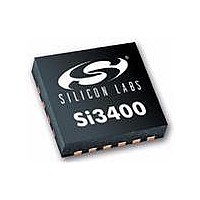
SI3402-A-GM Silicon Laboratories Inc, SI3402-A-GM Datasheet - Page 15

SI3402-A-GM
Manufacturer Part Number
SI3402-A-GM
Description
IC POE PD LOW EMI SW REG 20VQFN
Manufacturer
Silicon Laboratories Inc
Type
Power over Ethernet Switch (PoE)r
Datasheet
1.SI3402-A-GMR.pdf
(22 pages)
Specifications of SI3402-A-GM
Package / Case
20-VQFN
Applications
IP Phones, Power over LAN, Network Routers and Switches
Internal Switch(s)
Yes
Current Limit
470mA
Voltage - Supply
2.8 V ~ 57 V
Operating Temperature
-40°C ~ 85°C
Mounting Type
Surface Mount
Product
PoE / LAN Solutions
Supply Voltage (max)
57 V
Supply Voltage (min)
2.8 V
Power Dissipation
1.2 W
Operating Temperature Range
- 40 C to + 85 C
Mounting Style
SMD/SMT
Operating Temperature (min)
-40C
Operating Temperature Classification
Industrial
Operating Temperature (max)
85C
Rad Hardened
No
Lead Free Status / RoHS Status
Lead free / RoHS Compliant
Lead Free Status / RoHS Status
Lead free / RoHS Compliant, Lead free / RoHS Compliant
Available stocks
Company
Part Number
Manufacturer
Quantity
Price
Company:
Part Number:
SI3402-A-GM
Manufacturer:
SILICON
Quantity:
201
Company:
Part Number:
SI3402-A-GMR
Manufacturer:
DALLAS
Quantity:
101
Part Number:
SI3402-A-GMR
Manufacturer:
SILICON LABS/èٹ¯ç§‘
Quantity:
20 000
3.3.1. Switcher Startup
The switching regulator is disabled until the hotswap
interface has both identified itself to the PSE and
charged the supply capacitor needed to filter the
switching regulator's high-current transients. Once the
supply capacitor is charged, the hotswap controller
engages the internal bias currents and supplies used by
the switcher. Additionally, the soft-start current begins to
charge the external soft-start capacitor.
The voltage developed across the soft-start capacitor
serves as the error amplifier's reference in the non-
isolated application. Ramping this voltage slowly allows
the switching regulator to bring up the regulated output
voltage in a controlled manner. Controlling the initial
startup of the regulated voltage restrains power
dissipation in the switching FET and prevents overshoot
and ringing in the output supply voltage.
In the isolated mode, a capacitor connected between
pins ISOSSFT and VSSA slowly ramps the duty cycle
clamp in the PWM circuit. Tie this pin to VDD if it is not
used.
3.3.2. Switching Regulator Operation
The switching regulator of the Si3402 is constant-
frequency,
controller
optimized for the output power range defined by the
802.3 specification.
Once the hotswap interface has ensured proper turn-on
of the switching regulator controller, the switcher is fully
operational. An internal free-running oscillator and
internal precision voltage reference are fed into the
pulse-width modulator. The output of the error amplifier
(either internal for non-isolated applications or external
for isolated applications) is also routed into the PWM
and determines the slicing of the oscillator.
integrated
pulse-width-modulated
with
switching
(PWM),
power
FETs
and
Rev. 1.1
The PWM controls the switching FET drive circuitry. A
significant advantage of integrating the switching power
FET onto the same monolithic IC as the switching
regulator controller is the ability to precisely adjust the
drive strength and timing to the FET's sizable gate,
resulting in high regulator efficiency. Furthermore,
current-limiting circuitry prevents the switching FET
from sinking too much current, dissipating too much
power, and becoming damaged. Thermal overload
protection provides a secondary level of protection.
The flexibility of the Si3402's switching regulator allows
the system designer to realize either the isolated or non-
isolated application circuitry using a single device. In
operation, the integration of the switching FET allows
tighter control and more efficient operation than a
general-purpose switching regulator coupled with a
general-purpose external FET.
3.3.3. Flyback Snubber
Extremely high voltages can be generated by the
inductive kick associated with the leakage inductance of
the primary side of the flyback transformer used in
isolated applications.
Refer to “AN296: Using the Si3400/1/2 PoE PD
Controller in Isolated and Non-Isolated Designs” for
more information on the snubber.
Si3402
15


