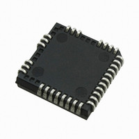
IRS26302DJPBF International Rectifier, IRS26302DJPBF Datasheet - Page 24

IRS26302DJPBF
Manufacturer Part Number
IRS26302DJPBF
Description
IC BRIDGE +1 GATE DVR 3PH 44PLCC
Manufacturer
International Rectifier
Datasheet
1.IRS26302DJTRPBF.pdf
(51 pages)
Specifications of IRS26302DJPBF
Configuration
3 Phase Bridge
Input Type
Non-Inverting
Delay Time
320ns
Current - Peak
200mA
Number Of Configurations
1
Number Of Outputs
3
High Side Voltage - Max (bootstrap)
600V
Voltage - Supply
10 V ~ 20 V
Operating Temperature
-40°C ~ 125°C
Mounting Type
Surface Mount
Package / Case
44-PLCC (32 Leads)
Number Of Drivers
6
Driver Configuration
Non-Inverting
Driver Type
High and Low Side
Input Logic Level
CMOS/TTL
Rise Time
190ns
Fall Time
75ns
Propagation Delay Time
710ns
Peak Output Current
350mA
Power Dissipation
4.6W
Operating Supply Voltage (min)
10V
Turn Off Delay Time
50ns
Turn On Delay Time (max)
50ns
Operating Temp Range
-40C to 125C
Operating Temperature Classification
Automotive
Mounting
Surface Mount
Pin Count
32
Package Type
PLCC
Lead Free Status / RoHS Status
Lead free / RoHS Compliant
Available stocks
Company
Part Number
Manufacturer
Quantity
Price
Company:
Part Number:
IRS26302DJPBF
Manufacturer:
International Rectifier
Quantity:
10 000
be selected such the voltage V
the maximum allowable temperature is reached. The voltage of the ITRIP pin should not be allowed to exceed 5 V.
(e.g., DL4148) can be used. This network is shown in Figure 16; the OR-ing diodes have been labeled D
Truth Table: Undervoltage lockout, ITRIP, GF, PCFtrip and ENABLE
Table 4 provides the truth table for the IRS26302DJ. The first line shows that the UVLO for V
FAULT output has gone low and the gate drive outputs have been disabled. V
when V
The second case shows that the UVLO for V
disabled. After V
of HIN. The third case shows the normal operation of the HVIC. The fourth case illustrates that the ITRIP trip
threshold has been reached and that the gate drive outputs have been disabled and a fault has been reported
through the fault pin. Same behavior if GF or PCFtrip threshold has been reached. In the last case, the HVIC has
received a command through the EN input to shutdown; as a result, the gate drive outputs have been disabled.
When using both the over-current protection and over-temperature protection with the ITRIP input, OR-ing diodes
Figure 15: Programming over-temperature protection
www.irf.com
UVLO V
UVLO V
operation
PCFtrip
Normal
ITRIP
fault
GF
EN
CC
is greater than V
CC
BS
Table 4: IRS26302DJ UVLO, ITRIP, GF, PCFtrip, EN, RCIN, & FAULT truth table
< V
BS
VCC
15 V
15 V
15 V
15 V
15 V
15 V
CCUV
exceeds the V
< V
CCUV
VBS
15 V
15 V
15 V
15 V
15 V
---
BSUV
, the FAULT output returns to the high impedance state.
X
should reach the threshold voltage (V
BSUV
>V
ITRIP
0 V
0 V
0 V
0 V
0 V
---
ITRIP
threshold , HO will stay low until the HVIC input receives a new rising transition
GFth
BS
0 V
0 V
0 V
0 V
0 V
GF
---
<
has been tripped and that the high-side gate drive outputs have been
<PCF
PFC
trip
0 V
0 V
0 V
0 V
0 V
---
th
24
Figure 16: Using over-current protection and over-
5 V
5 V
5 V
5 V
5 V
0 V
EN
---
RCIN
High
High
High
High
IT,TH+
Low
Low
Low
) of the ITRIP functionality by the time that
temperature protection
FAULT
High Z
High Z
High Z
CCUV
0
0
0
0
is not latched in this case and
© 2009 International Rectifier
LIN
LIN
LO
0
0
0
0
0
IRS26302DJ
CC
has been tripped; the
HIN
HO
0
0
0
0
0
0
1
PCFout
PCFIN
and D
0
0
0
0
0
0
2
.


