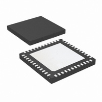
LM96194CISQ/NOPB National Semiconductor, LM96194CISQ/NOPB Datasheet - Page 64

LM96194CISQ/NOPB
Manufacturer Part Number
LM96194CISQ/NOPB
Description
IC TRUTHERM HDWR MONITOR 48-LLP
Manufacturer
National Semiconductor
Series
PowerWise®, TruTherm®r
Datasheet
1.LM96194CISQNOPB.pdf
(106 pages)
Specifications of LM96194CISQ/NOPB
Function
Fan Control, Temp Monitor
Topology
ADC (Sigma Delta), Comparator, Fan Control, Multiplexer, Register Bank
Sensor Type
External & Internal
Sensing Temperature
-40°C ~ 85°C, External Sensor
Output Type
SMBus™
Output Alarm
No
Output Fan
Yes
Voltage - Supply
3 V ~ 3.6 V
Operating Temperature
-40°C ~ 85°C
Mounting Type
Surface Mount
Package / Case
48-LLP
Lead Free Status / RoHS Status
Lead free / RoHS Compliant
Other names
LM96194CISQTR
www.national.com
Register
Address
16.11.8 Register 6E–75h Fan Tachometer Readings
The 14-bit fan tach readings indicate the number of 22.5 kHz clock periods that occurred during two full periods of the tachometer
input signal. Most fans produce two tachometer pulses per full revolution. These registers must be updated at least once every
second.
The fan tachometer reading registers must always return an accurate fan tachometer measurement, even when a fan is disabled
or non-functional. 3FFFh indicates that the fan is stalled, not spinning fast enough to measure, or the tachometer input is not
connected to a valid signal.
If the pulses per revolution of the fan is known, the RPM can be calculated with the following equation:
RPM= 22500 cycles/sec * 60 sec/min * 2 pulses / COUNT cycles / PULSES_PER_REV
where:
PULSES_PER_REV
COUNT
6Eh
6Fh
70h
71h
72h
73h
74h
75h
1:0
7:2
7:0
Bit
T3ST[1:0], or T4ST[1:0]
T1ST[1:0], T2ST[1:0],
Read/
Write
TACH1[13:6], TACH2[13:6],
R
R
R
R
R
R
R
R
TACH3[13:6], TACH4[13:6]
TACH1[5:0], TACH2[5:0],
TACH3[5:0], TACH4[5:0]
00
01
10
11
T1ST[1:0], T2ST[1:0],
T3ST[1:0], T4ST[1:0]
Name
Fan Tach 1
Fan Tach 1
Fan Tach 2
Fan Tach 2
Fan Tach 3
Fan Tach 3
Fan Tach 4
Fan Tach 4
Register
Name
MSB
MSB
MSB
MSB
LSB
LSB
LSB
LSB
State of Fan Control Circuitry
Normal Mode (Smart Tach Mode disabled)
Reserved
Smart Tach Mode 1, less accurate with most stable Fan RPM
Smart Tach Mode 2, most accurate with least stable Fan RPM
= the number of pulses that the fan produces per revolution
= The 14-bit value read from the tach register
Bit 7
Read/Write
R
R
R
Bit 6
Two bits for each tachometer reading that report the state of the fan control
circuitry used to acquire a reading. See table below for further clarification.
Least significant bit field of tachometer reading.
Most significant bit fielf of tachometer reading.
Bit 5
64
TACH1[5:0]
TACH2[5:0]
TACH3[5:0]
TACH4[5:0]
Bit 4
TACH1[13:6]
TACH2[13:6]
TACH3[13:6]
TACH4[13:6]
Bit 3
Description
Bit 2
Bit 1
T1ST[1:0]
T2ST[1:0]
T3ST[1:0]
T4ST[1:0]
Bit 0
Default
Value
00h
00h
00h
00h
00h
00h
00h
00h


