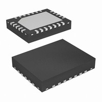
ISL8101IRZ Intersil, ISL8101IRZ Datasheet - Page 12

ISL8101IRZ
Manufacturer Part Number
ISL8101IRZ
Description
IC PWM CTRLR BUCK 2PHASE 24-QFN
Manufacturer
Intersil
Datasheet
1.ISL8101CRZ-T.pdf
(20 pages)
Specifications of ISL8101IRZ
Applications
Controller, Intel VRM9, VRM10, and AMD Hammer Applications
Voltage - Input
4.6 ~ 12 V
Number Of Outputs
1
Voltage - Output
0.6 ~ 2.3 V
Operating Temperature
-40°C ~ 85°C
Mounting Type
Surface Mount
Package / Case
24-VQFN Exposed Pad, 24-HVQFN, 24-SQFN, 24-DHVQFN
Lead Free Status / RoHS Status
Lead free / RoHS Compliant
OVERVOLTAGE PROTECTION
The ISL8101 benefits from a multi-tiered approach to
overvoltage protection.
A pre-POR mechanism is at work while the chip does not
have sufficient bias voltage to initiate an active response to
an OV situation. Thus, while VCC is below its POR level, the
lower drives are three-stated and internal 5kΩ (typically)
resistors are connected from PHASE to their respective
LGATE pins. As a result, output voltage, duplicated at the
PHASE nodes via the output inductors, is effectively
clamped at the lower MOSFETs’ threshold level. This
approach ensures no catastrophic output voltage can be
developed at the output of an ISL8101-based regulator (for
most typical applications).
The pre-POR mechanism is removed once the bias is above
the POR level, and a fixed-threshold OVP goes into effect.
Based on the specific chip configuration, the OVP goes into
effect once the voltage sensed at the FB pin exceeds about
1.65V (Hammer/VR10) or 1.95V (VR9 configuration). Should
the output voltage exceed these thresholds, the lower
MOSFETs are turned on.
During soft-start, the OVP threshold changes to the higher of
the fixed threshold (1.65V/1.95V) or the DAC setting plus
200mV. At the end of the soft-start, the OVP threshold
changes to the DAC setting plus 200mV.
In any of the described post-POR functionality, OVP results
in the turn-on of the lower MOSFETs. Once turned on, the
lower MOSFETs are only turned off when the output voltage
drops below the OV comparator’s hysteretic threshold. The
OVP process repeats if the voltage rises back above the
designated threshold. The occurrence of an OVP event does
not latch the controller; should the phenomenon be
transitory, the controller resumes normal operation following
such an event.
ON/OFF CONTROL
The internal power-on reset circuit (POR) prevents the
ISL8101 from starting before the bias voltage at VCC and
PVCC reach the rising POR thresholds, as defined in
“Electrical Specifications” on page 4. The POR levels are
sufficiently high to guarantee that all parts of the ISL8101
can perform their functions properly once bias is applied to
the part. While bias is below the rising POR thresholds, the
controlled MOSFETs are kept in an off state.
A secondary disablement feature is available via the
threshold-sensitive enable input (ENLL). This optional
feature prevents the ISL8101 from operating until a certain
other voltage rail is available and above some selectable
threshold. For example, when down-converting off a 12V
input, it may be desirable the ISL8101-based converter does
not start up until the power input is sufficiently high. The
schematic in Figure 6 demonstrates coordination of the
ISL8101 with such a rail; the resistor components are
12
ISL8101
ISL8101
chosen to enable the ISL8101 as the 12V input exceeds
approximately 9.75V. Additionally, an open-drain or open-
collector device can be used to wire-AND a second (or
multiple) control signal, as shown in Figure 6. To defeat the
threshold-sensitive enable, connect ENLL to VCC directly or
via a pull-up resistor.
The ‘11111’ VID code is reserved as a signal to the controller
that no load is present. The controller is disabled while
receiving this VID code and will subsequently start up upon
receiving any other code.
In summary, for the ISL8101 to operate, the following
conditions need be met: V
than their respective POR thresholds, the voltage at ENLL
must be greater than 0.61V, and VID has to be different than
‘11111’. Once all these conditions are met, the controller
immediately initiates a soft-start sequence.
SOFT-START
The soft-start function allows the converter to bring up the
output voltage in a controlled fashion, resulting in a linear
ramp-up. Following a delay of 16 PHASE clock cycles (about
70µs) between enabling the chip and the start of the ramp,
the output voltage progresses at a fixed rate of 12.5mV per
16 PHASE clock cycles.
Thus, the soft-start period (not including the 70µs wait) up to
a given voltage, V
where V
switching frequency (typically 222kHz).
The ISL8101 also has the ability to start-up into a
pre-charged output, without causing any unnecessary
disturbance. The FB pin is monitored during soft-start, and
should it be higher than the equivalent internal ramping
reference voltage, the output drives hold both MOSFETs off.
Once the internal ramping reference exceeds the FB pin
t
SS
FIGURE 6. START-UP COORDINATION USING THRESHOLD-
CIRCUIT
=
POR
V
---------------------------------
DAC
DAC
f
S
⋅
SENSITIVE ENABLE (ENLL) PIN
is the DAC-set VID voltage, and f
COMPARATOR
1280
ENABLE
DAC
ISL8101
+
-
0.61V
, can be approximated by Equation 7.
CC
ENLL
V
and P
CC
+5V
EXTERNAL CIRCUIT
15kΩ
VCC
1kΩ
+12V
must be greater
S
is the
July 28, 2008
(EQ. 7)
ON
FN9223.1
OFF


