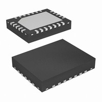
ISL8101IRZ Intersil, ISL8101IRZ Datasheet - Page 13

ISL8101IRZ
Manufacturer Part Number
ISL8101IRZ
Description
IC PWM CTRLR BUCK 2PHASE 24-QFN
Manufacturer
Intersil
Datasheet
1.ISL8101CRZ-T.pdf
(20 pages)
Specifications of ISL8101IRZ
Applications
Controller, Intel VRM9, VRM10, and AMD Hammer Applications
Voltage - Input
4.6 ~ 12 V
Number Of Outputs
1
Voltage - Output
0.6 ~ 2.3 V
Operating Temperature
-40°C ~ 85°C
Mounting Type
Surface Mount
Package / Case
24-VQFN Exposed Pad, 24-HVQFN, 24-SQFN, 24-DHVQFN
Lead Free Status / RoHS Status
Lead free / RoHS Compliant
potential, the output drives are enabled, allowing the output
to ramp from the pre-charged level to the final level dictated
by the DAC setting. Should the output be pre-charged to a
level exceeding the DAC setting, the output drives are
enabled at the end of the soft-start period, leading to an
abrupt correction in the output voltage down to the DAC-set
level.
FREQUENCY COMPENSATION
The ISL8101 multiphase converter behaves in a similar
manner to a voltage-mode controller. This section highlights
the design consideration for a voltage-mode controller requiring
external compensation. To address a broad range of
applications, a type-3 feedback network is recommended.
Figure 8 highlights the voltage-mode control loop for a
synchronous-rectified buck converter, applicable, with a small
number of adjustments, to the multiphase ISL8101 circuit. The
output voltage (V
VREF, level. The error amplifier output (COMP pin voltage) is
compared with the oscillator (OSC) modified saw-tooth wave to
provide a pulse-width modulated wave with an amplitude of V
at the PHASE node. The PWM wave is smoothed by the output
filter (L and C). The output filter capacitor bank’s equivalent
series resistance is represented by the series resistor E.
The modulator transfer function is the small-signal transfer
function of V
gain, given by d
filter, with a double pole break frequency at F
F
individual channel inductance and its DCR divided by 2
(equivalent parallel value of the two output inductors), while C
and E represents the total output capacitance and its
equivalent series resistance (see Equation 8).
F
CE
GND>
GND>
LC
FIGURE 7. SOFT-START WAVEFORMS FOR ISL8101-BASED
=
. For the purpose of this analysis, L and D represent the
---------------------------
2π
OUTPUT PRECHARGED
⋅
BELOW DAC LEVEL
1
L C
OUT
OUTPUT PRECHARGED
⋅
MULTIPHASE CONVERTER
ABOVE DAC LEVEL
MAX
OUT
/V
T1
COMP
V
T2
) is regulated to the reference voltage,
IN
/V
. This function is dominated by a DC
OSC
F
CE
13
, and shaped by the output
=
----------------------- -
2π C E
⋅
T3
1
⋅
V
LC
OUT
ENLL (5V/DIV)
and a zero at
(0.5V/DIV)
(EQ. 8)
IN
ISL8101
ISL8101
The compensation network consists of the error amplifier
(internal to the ISL8101) and the external R
components. The goal of the compensation network is to
provide a closed loop transfer function with high 0dB crossing
frequency (F
margin (better than 45°). Phase margin is the difference
between the closed loop phase at F
9,10, 11, and 12 relate the compensation network’s poles,
zeros and gain to the components (R
C
poles and zeros of the compensation network:
1. Select a value for R
2. Calculate C
3
FIGURE 8. VOLTAGE-MODE BUCK CONVERTER
) (see Figure 8). Use the following guidelines for locating the
value for R
at 0.1 to 0.75 of F
desired number). The higher the quality factor of the output
filter and/or the higher the ratio F
frequency (to maximize phase boost).
R2
C
CIRCUIT
1
PWM
=
=
-------------------------------------------- -
d
---------------------------------------------- -
2π R
COMP
V
MAX
0
OSC
⋅
; typically 0.1 to 0.3 of F
COMPENSATION DESIGN
2
1
2
HALF-BRIDGE
⋅
such that F
for desired converter bandwidth (F
OSCILLATOR
V
⋅
⋅
V
1
0.5 F
R
IN
OSC
E/A
DRIVE
1
LC
⋅
⋅
⋅
R
F
F
ISL8101
2
LC
1
0
(to adjust, change the 0.5 factor to
LC
C
+
(1kΩ to 5kΩ, typically). Calculate
-
2
V
Z1
REF
C
1
is placed at a fraction of the F
PHASE
UGATE
FB
LGATE
EXTERNAL CIRCUIT
0dB
CE
1
SW
, R
/F
and 180
) and adequate phase
V
2
LC
R
IN
, R
1
3
, the lower the F
-R
3
R
L
1
3
, C
, C
°
C
. Equations
1
3
1
, C
-C
V
D
0
July 28, 2008
OUT
2
C
(EQ. 10)
3
).
E
, and
(EQ. 9)
FN9223.1
LC
Z1
,


