ADZS-21262-1-EZEXT Analog Devices Inc, ADZS-21262-1-EZEXT Datasheet - Page 13
ADZS-21262-1-EZEXT
Manufacturer Part Number
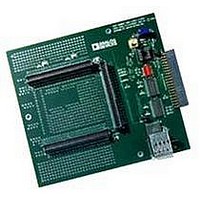
ADZS-21262-1-EZEXT
Description
BOARD DAUGHTER FOR ADSP-21262
Manufacturer
Analog Devices Inc
Datasheet
1.ADSP-21363KSWZ-1AA.pdf
(56 pages)
Specifications of ADZS-21262-1-EZEXT
Accessory Type
DSP
Silicon Manufacturer
Analog Devices
Core Architecture
SHARC
Features
Expansion Interface, High Speed Converter (HSC) Interface
Kit Contents
Board Docs
Silicon Family Name
SHARC
Silicon Core Number
ADSP-21262
Rohs Compliant
Yes
Lead Free Status / RoHS Status
Lead free / RoHS Compliant
For Use With/related Products
ADSP-21262
Lead Free Status / RoHS Status
Lead free / RoHS Compliant, Lead free / RoHS Compliant


Table 6. Pin Descriptions (Continued)
1
2
3
4
Pin
BOOT_CFG1–0
RESETOUT
RESET
TCK
TMS
TDI
TDO
TRST
EMU
V
V
A
A
GND
The following symbols appear in the Type column of
S = synchronous, (A/D) = active drive, (O/D) = open drain, and T = three-state, (pd) = pull-down resistor, (pu) = pull-up resistor.
RD, WR, and ALE are three-stated (and not driven) only when RESET is active.
Output only is a three-state driver with its output path always enabled.
Input only is a three-state driver with both output path and pull-up disabled.
Three-state is a three-state driver with pull-up disabled.
DDINT
DDEXT
VDD
VSS
Type
I
O
I/A
I
I/S
(pu)
I/S
(pu)
O
I/A
(pu)
O (O/D)
(pu)
P
P
P
G
G
ADSP-21362/ADSP-21363/ADSP-21364/ADSP-21365/ADSP-21366
State During and
After Reset
Input only
Output only
Input only
Input only
Three-state with
pull-up enabled
Three-state with
pull-up enabled
Three-state
Three-state with
pull-up enabled
Three-state with
pull-up enabled
3
4
Rev. G | Page 13 of 56 | March 2011
Table
Function
Boot Configuration Select. This pin is used to select the boot mode for the processor.
The BOOT_CFG pins must be valid before reset is asserted. For a description of the boot
mode, refer to the ADSP-2136x SHARC Processor Hardware Reference .
Reset Out. Drives out the core reset signal to an external device.
Processor Reset. Resets the ADSP-2136x to a known state. Upon deassertion, there is a
4096 CLKIN cycle latency for the PLL to lock. After this time, the core begins program
execution from the hardware reset vector address. The RESET input must be asserted
(low) at power-up.
Test Clock (JTAG). Provides a clock for JTAG boundary scan. TCK must be asserted
(pulsed low) after power-up or held low for proper operation of the processors.
Test Mode Select (JTAG). Used to control the test state machine. TMS has a 22.5 kΩ
internal pull-up resistor.
Test Data Input (JTAG). Provides serial data for the boundary scan logic. TDI has a 22.5
kΩ internal pull-up resistor.
Test Data Output (JTAG). Serial scan output of the boundary scan path.
Test Reset (JTAG). Resets the test state machine. TRST must be asserted (pulsed low)
after power-up or held low for proper operation of the ADSP-2136x. TRST has a 22.5 kΩ
internal pull-up resistor.
Emulation Status. Must be connected to the processor’s JTAG emulators target board
connector only. EMU has a 22.5 kΩ internal pull-up resistor.
Core Power Supply. Nominally +1.2 V dc for the K, B grade models, and 1.0 V dc for the
Y grade models, and supplies the processor’s core.
I/O Power Supply. Nominally +3.3 V dc.
Analog Power Supply. Nominally +1.2 V dc for the K, B grade models, and 1.0 V dc for
the Y grade models, and supplies the processor’s internal PLL (clock generator). This pin
has the same specifications as V
more information, see Power Supplies on Page 8.
Analog Power Supply Return.
Power Supply Return.
6: A = asynchronous, G = ground, I = input, O = output, P = power supply,
DDINT
, except that added filtering circuitry is required.
For
Related parts for ADZS-21262-1-EZEXT
Image
Part Number
Description
Manufacturer
Datasheet
Request
R

Part Number:
Description:
BOARD DAUGHTER EZ EXTENDER
Manufacturer:
Analog Devices Inc
Datasheet:

Part Number:
Description:
±1.7g Dual-Axis IMEMS Accelerometer Evaluation Board
Manufacturer:
Analog Devices Inc
Datasheet:

Part Number:
Description:
Inertial Sensor Evaluation System
Manufacturer:
Analog Devices Inc
Datasheet:
Part Number:
Description:
Manufacturer:
Analog Devices Inc
Datasheet:
Part Number:
Description:
Manufacturer:
Analog Devices Inc
Datasheet:
Part Number:
Description:
Manufacturer:
Analog Devices Inc
Datasheet:
Part Number:
Description:
Manufacturer:
Analog Devices Inc
Datasheet:
Part Number:
Description:
Manufacturer:
Analog Devices Inc
Datasheet:
Part Number:
Description:
Manufacturer:
Analog Devices Inc
Datasheet:
Part Number:
Description:
Manufacturer:
Analog Devices Inc
Datasheet:
Part Number:
Description:
Manufacturer:
Analog Devices Inc
Datasheet:
Part Number:
Description:
Manufacturer:
Analog Devices Inc
Datasheet:
Part Number:
Description:
Manufacturer:
Analog Devices Inc
Datasheet: