ADZS-21262-1-EZEXT Analog Devices Inc, ADZS-21262-1-EZEXT Datasheet - Page 16
ADZS-21262-1-EZEXT
Manufacturer Part Number
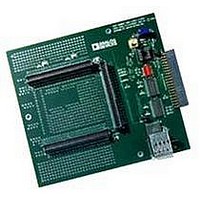
ADZS-21262-1-EZEXT
Description
BOARD DAUGHTER FOR ADSP-21262
Manufacturer
Analog Devices Inc
Datasheet
1.ADSP-21363KSWZ-1AA.pdf
(56 pages)
Specifications of ADZS-21262-1-EZEXT
Accessory Type
DSP
Silicon Manufacturer
Analog Devices
Core Architecture
SHARC
Features
Expansion Interface, High Speed Converter (HSC) Interface
Kit Contents
Board Docs
Silicon Family Name
SHARC
Silicon Core Number
ADSP-21262
Rohs Compliant
Yes
Lead Free Status / RoHS Status
Lead free / RoHS Compliant
For Use With/related Products
ADSP-21262
Lead Free Status / RoHS Status
Lead free / RoHS Compliant, Lead free / RoHS Compliant


ADSP-21362/ADSP-21363/ADSP-21364/ADSP-21365/ADSP-21366
The VCO frequency is calculated as follows:
f
f
where:
f
PLLM = Multiplier value programmed in the PMCTL register.
During reset, the PLLM value is derived from the ratio selected
using the CLK_CFG pins in hardware.
PLLN = 1, 2, 4, 8 based on the PLLD value programmed on the
PMCTL register. During reset this value is 1.
f
f
f
VCO
CCLK
VCO
INPUT
INPUT
INPUT
• The product of CLKIN and PLLM must never exceed f
(max) in
(INDIV = 1).
= 2 × PLLM × f
= VCO output
= (2 × PLLM × f
= Input frequency to the PLL.
= CLKIN when the input divider is disabled or
= CLKIN ÷ 2 when the input divider is enabled
Table 11
XTAL
INPUT
INPUT
if the input divider is enabled
BUF
CLKIN
) ÷ (2 × PLLN)
4096 CLKIN
DELAY OF
CYCLES
*CLKOUT (TEST ONLY) FREQUENCY IS THE SAME AS f
THIS SIGNAL IS NOT SPECIFIED OR SUPPORTED FOR ANY DESIGN.
DIVIDER
PMCTL
CLKIN
(INDIV)
Figure 5. Core Clock and System Clock Relationship to CLKIN
f
INPUT
Rev. G | Page 16 of 56 | March 2011
f
VCO
VCO
FILTER
LOOP
÷ (2 × PLLM)
PMCTL (2 × PLLM)
CLKOUT (TEST ONLY)*
CLK_CFGx/
PLL
VCO
Note the definitions of the clock periods that are a function of
CLKIN and the appropriate ratio control shown in
of the timing specifications for the ADSP-2136x peripherals are
defined in relation to t
tion for each peripheral’s timing information.
Table 9. Clock Periods
Figure 5
lator or crystal. The shaded divider/multiplier blocks denote
where clock ratios can be set through hardware or software
using the power management control register (PMCTL). For
more information, refer to the ADSP-2136x SHARC Processor
Hardware Reference.
Timing
Requirements
t
t
t
CK
CCLK
PCLK
INPUT.
f
VCO
shows core to CLKIN relationships with external oscil-
DIVIDER
PMCTL
(PLLD)
PLL
f
CCLK
PMCTL (CLKOUTEN)
PCLK
(PLLBP)
PMCTL
Description
CLKIN Clock Period
Processor Core Clock Period
Peripheral Clock Period = 2 × t
. Refer to the peripheral specific sec-
DIVIDE
BY 2
BUF
CCLK
PCLK
Table
CCLK
9. All
Related parts for ADZS-21262-1-EZEXT
Image
Part Number
Description
Manufacturer
Datasheet
Request
R

Part Number:
Description:
BOARD DAUGHTER EZ EXTENDER
Manufacturer:
Analog Devices Inc
Datasheet:

Part Number:
Description:
±1.7g Dual-Axis IMEMS Accelerometer Evaluation Board
Manufacturer:
Analog Devices Inc
Datasheet:

Part Number:
Description:
Inertial Sensor Evaluation System
Manufacturer:
Analog Devices Inc
Datasheet:
Part Number:
Description:
Manufacturer:
Analog Devices Inc
Datasheet:
Part Number:
Description:
Manufacturer:
Analog Devices Inc
Datasheet:
Part Number:
Description:
Manufacturer:
Analog Devices Inc
Datasheet:
Part Number:
Description:
Manufacturer:
Analog Devices Inc
Datasheet:
Part Number:
Description:
Manufacturer:
Analog Devices Inc
Datasheet:
Part Number:
Description:
Manufacturer:
Analog Devices Inc
Datasheet:
Part Number:
Description:
Manufacturer:
Analog Devices Inc
Datasheet:
Part Number:
Description:
Manufacturer:
Analog Devices Inc
Datasheet:
Part Number:
Description:
Manufacturer:
Analog Devices Inc
Datasheet:
Part Number:
Description:
Manufacturer:
Analog Devices Inc
Datasheet: