ADZS-21262-1-EZEXT Analog Devices Inc, ADZS-21262-1-EZEXT Datasheet - Page 45
ADZS-21262-1-EZEXT
Manufacturer Part Number
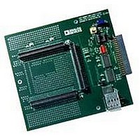
ADZS-21262-1-EZEXT
Description
BOARD DAUGHTER FOR ADSP-21262
Manufacturer
Analog Devices Inc
Datasheet
1.ADSP-21363KSWZ-1AA.pdf
(56 pages)
Specifications of ADZS-21262-1-EZEXT
Accessory Type
DSP
Silicon Manufacturer
Analog Devices
Core Architecture
SHARC
Features
Expansion Interface, High Speed Converter (HSC) Interface
Kit Contents
Board Docs
Silicon Family Name
SHARC
Silicon Core Number
ADSP-21262
Rohs Compliant
Yes
Lead Free Status / RoHS Status
Lead free / RoHS Compliant
For Use With/related Products
ADSP-21262
Lead Free Status / RoHS Status
Lead free / RoHS Compliant, Lead free / RoHS Compliant


THERMAL CHARACTERISTICS
The processor is rated for performance over the temperature
range specified in Operating Conditions
Table 42
JEDEC standards JESD51-2 and JESD51-6 and the junction-to-
board measurement complies with JESD51-8. Test board and
thermal via design comply with JEDEC standards JESD51-9
(BGA) and JESD51-5 (LQFP_EP). The junction-to-case mea-
surement complies with MIL-STD-883. All measurements use a
2S2P JEDEC test board.
Industrial applications using the BGA package require thermal
vias, to an embedded ground plane, in the PCB. Refer to JEDEC
standard JESD51-9 for printed circuit board thermal ball land
and thermal via design information.
Industrial applications using the LQFP_EP package require
thermal trace squares and thermal vias, to an embedded ground
plane, in the PCB. Refer to JEDEC standard JESD51-5 for more
information.
To determine the junction temperature of the device while on
the application PCB, use:
where:
T
T
package
Ψ
is the typical value from
P
ADSP-21362 SHARC Processors (EE-277) for more information.
Values of θ
design considerations.
D
J
T
JT
= junction temperature (
= case temperature (
= power dissipation. See Estimating Power for the
= junction-to-top (of package) characterization parameter
Figure 42. Typical Output Delay or Hold versus Load Capacitance
- 2
- 4
10
8
6
4
2
0
through
0
JA
are provided for package comparison and PCB
y = 0.0488x - 1.5923
Table 44
T
(at Ambient Temperature)
J
50
°
=
C) measured at the top center of the
Table 42
T
airflow measurements comply with
ADSP-21362/ADSP-21363/ADSP-21364/ADSP-21365/ADSP-21366
°
C)
T
LOAD CAPACITANCE (pF)
+
through
100
JT
P
on Page
D
Table
150
44.
14.
Rev. G | Page 45 of 56 | March 2011
200
Values of θ
design considerations when an exposed pad is required. Note
that the thermal characteristics values provided in
through
Table 42. Thermal Characteristics for BGA (No Thermal vias
in PCB)
Table 43. Thermal Characteristics for BGA (Thermal vias in
PCB)
Table 44. Thermal Characteristics for LQFP_EP (with
Exposed Pad Soldered to PCB)
Parameter
θ
θ
θ
θ
Ψ
Ψ
Ψ
Parameter
θ
θ
θ
θ
Ψ
Ψ
Ψ
Parameter
θ
θ
θ
θ
Ψ
Ψ
Ψ
JA
JMA
JMA
JC
JA
JMA
JMA
JC
JA
JMA
JMA
JC
JT
JMT
JMT
JT
JMT
JMT
JT
JMT
JMT
Table 44
JC
are provided for package comparison and PCB
Condition
Airflow = 0 m/s
Airflow = 1 m/s
Airflow = 2 m/s
Airflow = 0 m/s
Airflow = 1 m/s
Airflow = 2 m/s
Condition
Airflow = 0 m/s
Airflow = 1 m/s
Airflow = 2 m/s
Airflow = 0 m/s
Airflow = 1 m/s
Airflow = 2 m/s
Condition
Airflow = 0 m/s
Airflow = 1 m/s
Airflow = 2 m/s
Airflow = 0 m/s
Airflow = 1 m/s
Airflow = 2 m/s
are modeled values.
Typical
25.40
21.90
20.90
5.07
0.140
0.330
0.410
Typical
23.40
20.00
19.20
5.00
0.130
0.300
0.360
Typical
16.80
14.20
13.50
7.25
0.51
0.72
0.80
Table 42
Unit
°C/W
°C/W
°C/W
°C/W
°C/W
°C/W
°C/W
Unit
°C/W
°C/W
°C/W
°C/W
°C/W
°C/W
°C/W
Unit
°C/W
°C/W
°C/W
°C/W
°C/W
°C/W
°C/W
Related parts for ADZS-21262-1-EZEXT
Image
Part Number
Description
Manufacturer
Datasheet
Request
R

Part Number:
Description:
BOARD DAUGHTER EZ EXTENDER
Manufacturer:
Analog Devices Inc
Datasheet:

Part Number:
Description:
±1.7g Dual-Axis IMEMS Accelerometer Evaluation Board
Manufacturer:
Analog Devices Inc
Datasheet:

Part Number:
Description:
Inertial Sensor Evaluation System
Manufacturer:
Analog Devices Inc
Datasheet:
Part Number:
Description:
Manufacturer:
Analog Devices Inc
Datasheet:
Part Number:
Description:
Manufacturer:
Analog Devices Inc
Datasheet:
Part Number:
Description:
Manufacturer:
Analog Devices Inc
Datasheet:
Part Number:
Description:
Manufacturer:
Analog Devices Inc
Datasheet:
Part Number:
Description:
Manufacturer:
Analog Devices Inc
Datasheet:
Part Number:
Description:
Manufacturer:
Analog Devices Inc
Datasheet:
Part Number:
Description:
Manufacturer:
Analog Devices Inc
Datasheet:
Part Number:
Description:
Manufacturer:
Analog Devices Inc
Datasheet:
Part Number:
Description:
Manufacturer:
Analog Devices Inc
Datasheet:
Part Number:
Description:
Manufacturer:
Analog Devices Inc
Datasheet: