MCP1631RD-MCC2 Microchip Technology, MCP1631RD-MCC2 Datasheet - Page 14
MCP1631RD-MCC2
Manufacturer Part Number
MCP1631RD-MCC2
Description
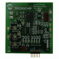
REFERENCE DESIGN MCP1631HV
Manufacturer
Microchip Technology
Datasheets
1.MCP1631VHVT-330EST.pdf
(34 pages)
2.MCP1631HV-330EST.pdf
(54 pages)
3.MCP1631RD-MCC2.pdf
(20 pages)
4.MCP1631RD-MCC2.pdf
(328 pages)
Specifications of MCP1631RD-MCC2
Main Purpose
Power Management, Battery Charger
Embedded
Yes, MCU, 8-Bit
Utilized Ic / Part
MCP1631HV, PIC16F883
Primary Attributes
1 ~ 2 Cell- Li-Ion, 1 ~ 5 Cell- NiCd/NiMH, 1 ~ 2 1W LEDs
Secondary Attributes
Status LEDs
Silicon Manufacturer
Microchip
Application Sub Type
Battery Charger
Kit Application Type
Power Management - Battery
Silicon Core Number
MCP1631HV, PIC16F883
Kit Contents
Board
Lead Free Status / RoHS Status
Lead free / RoHS Compliant
Lead Free Status / RoHS Status
Lead free / RoHS Compliant


MCP1631HV Multi-Chemistry Battery Charger Reference Design
DS51791A-page 10
FIGURE 2-4:
2.3.1.3
• Three push buttons are used to start a charge cycle, select chemistry and select
• S1 (ON/OFF) is used to start and stop the charge cycle or to enter the program-
• Press S2 (CHEM) to select the desired chemistry, indication is provided by red
• Press S3 (CELLS) to select the number of series cells, indication is provided by
• Once the desired chemistry and number of cells is selected, press S1 (ON/OFF)
• To start a charge cycle press and release S1. D3 (green) will be illuminated
• If the chemistry LED is not flashing and the Status LED is flashing, a fault
• Remove input voltage and check connections and verify the proper battery pack
• Once the problem is corrected, apply the input voltage, verify chemistry and # of
number of series cells. There are two LEDs, (red - NiMH, green - Li-Ion, red +
green - LED Driver) used to indicate chemistry type and four yellow LEDs to
indicate the number of series cells selected (D6, D7, D8, D9).
ming mode. When the input voltage is within the specified operating range (+5.3V
to +16V), press and hold the ON/OFF button for 5 seconds, all LEDs with the
exception of D3 should be illuminated. Release S1 and STATUS LED (D3) will be
flashing, indicating that the board is in programming mode.
LED D4 (Li-Ion) or green LED D5 (NiMH/NiCd) or both (LED Driver).
yellow LEDs D6 thru D9 where D6 = bit 0 and D9 = bit 3 of a 4-bit hexadecimal
value.
to store the settings. The selected chemistry LED and number of series cells LED
both should be illuminated.
indicating a charge cycle has begun, the selected chemistry LED should flash
slowly indicating normal charge cycle conditions.
condition has persisted for 5 attempts indicating that the charge cycle has
terminated.
chemistry and number of series cells.
cells LEDs and press S1 to start a charge cycle.
Note:
V
V
BAT+
BAT–
SELECTING BATTERY CHEMISTRY AND NUMBER OF CELLS
For single cell Li-Ion, a 3600 mA-Hr battery with internal protection circuitry
is recommended for evaluation. For NiMH charge cycle, Panasonic
HHR-210AA/B2B were used to develop the -dV/dt and +dT/dt termination
methods.
Simulated Battery Load.
+
-
1,000 µF
10V Al
2Ω
10W
© 2009 Microchip Technology Inc.
+
-
Variable
Power Supply
0V - 6V
Related parts for MCP1631RD-MCC2
Image
Part Number
Description
Manufacturer
Datasheet
Request
R

Part Number:
Description:
REFERENCE DESIGN FOR MCP1631HV
Manufacturer:
Microchip Technology
Datasheet:

Part Number:
Description:
REF DES BATT CHARG OR LED DRIVER
Manufacturer:
Microchip Technology
Datasheet:

Part Number:
Description:
Manufacturer:
Microchip Technology Inc.
Datasheet:
Part Number:
Description:
Manufacturer:
Microchip Technology Inc.
Datasheet:
Part Number:
Description:
Manufacturer:
Microchip Technology Inc.
Datasheet:
Part Number:
Description:
Manufacturer:
Microchip Technology Inc.
Datasheet:
Part Number:
Description:
Manufacturer:
Microchip Technology Inc.
Datasheet:
Part Number:
Description:
Manufacturer:
Microchip Technology Inc.
Datasheet:
Part Number:
Description:
Manufacturer:
Microchip Technology Inc.
Datasheet:
Part Number:
Description:
Manufacturer:
Microchip Technology Inc.
Datasheet: