MCP1631RD-MCC2 Microchip Technology, MCP1631RD-MCC2 Datasheet - Page 48
MCP1631RD-MCC2
Manufacturer Part Number
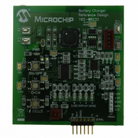
MCP1631RD-MCC2
Description
REFERENCE DESIGN MCP1631HV
Manufacturer
Microchip Technology
Datasheets
1.MCP1631VHVT-330EST.pdf
(34 pages)
2.MCP1631HV-330EST.pdf
(54 pages)
3.MCP1631RD-MCC2.pdf
(20 pages)
4.MCP1631RD-MCC2.pdf
(328 pages)
Specifications of MCP1631RD-MCC2
Main Purpose
Power Management, Battery Charger
Embedded
Yes, MCU, 8-Bit
Utilized Ic / Part
MCP1631HV, PIC16F883
Primary Attributes
1 ~ 2 Cell- Li-Ion, 1 ~ 5 Cell- NiCd/NiMH, 1 ~ 2 1W LEDs
Secondary Attributes
Status LEDs
Silicon Manufacturer
Microchip
Application Sub Type
Battery Charger
Kit Application Type
Power Management - Battery
Silicon Core Number
MCP1631HV, PIC16F883
Kit Contents
Board
Lead Free Status / RoHS Status
Lead free / RoHS Compliant
Lead Free Status / RoHS Status
Lead free / RoHS Compliant


MCP1631HV Multi-Chemistry Battery Charger Reference Design
DS51791A-page 44
C.6.3
1. In the mikroC
2. Double click on the
3. Scroll through the header file and locate “#define LION_SUPPORT”.
4. Scroll through the header file and locate “#define NIMH_SUPPORT”.
5. Scroll through the header file and locate “#define LED_DRIVER_SUPPORT”.
6. Scroll down to the “#IF (LED_DRIVER_SUPPORT == ENABLED) section of the
7. Set the LED_DRIVER_OVER_VOLTAGE to 3600 mV. (Overvoltage Shutdown
8. Set the LED_DRIVER_CONDITION_CURRENT to 10 mAh.
9. Set the LED_DRIVER_CONDITION_VOLTAGE to 0 mV. (Skips Conditioning
10. Set the LED_DRIVER_CURRENT to 300 mAh. (Constant Current mode).
11. Save the file (File | Save).
12. Compile (Project | Build).
13. Open MPLAB and load the workspace if it is not already loaded. (File | Open
14. Import the new “MCP1631HVBuckBoostBatteryChargerReferenceDesign.hex”
15. Download the file (Debugger | Program) and reset the processor (Debugger |
16. Run the new program (Debugger | Run).
17. Turn on the power supply and set the output voltage to 8V. Turn off the power
18. Connect the variable 8V supply (+) lead to the input connector (+) pin J1-1.
19. Connect the variable 8V supply (-) lead to the input connector (-) pin J1-2.
20. Connect the two 1 watt LED’s in series to the charger board J2 connector.
21. Turn on the variable 8V supply.
22. Press and hold the “ON/OFF” button on the charger board until the LED’s flash
23. Press and release the “CHEM” button until both the “NiMH” and “LiIon” LEDs are
24. Press and release the “# CELLS” button until the “1” “Display” LED is on and the
25. Press the “ON/OFF” button. The charger will exit Configuration mode.
26. Press the “ON/OFF” button. The charger will start charging the battery.
27. Press the “CHEM” button to display the current charger state in HEX. “0”
28. Press the “# CELLS” button to display the termination cause. No LED means no
the ‘.H’ file list.
“MULTICHEMISTRY_REF_DESIGN_BOARD_102_00232.H” file to open it.
Set it to “DISABLED”.
Set it to “DISABLED”.
Set it to “ENABLED”.
header file. The section contains LED Driver specific parameters.
value per LED).
State, not needed).
Workspace) MCP1631HVBuckBoostBatteryChargerReferenceDesign.mcw.
file. (File | Import)
Reset | Processor Reset).
supply.
(about 5 seconds). The board is now in Configuration Mode.
on.
“0”, “2” and “3” “Display” LED’s are off. The LED display now displays “2” in
Hexadecimal.
“Display” LED is LS Bit.
premature termination.
LED Driver Lab Exercise (Two 1 Watt LED’s in series)
™
“Project Summary” frame, click on the “H files” branch to expand
© 2009 Microchip Technology Inc.
Related parts for MCP1631RD-MCC2
Image
Part Number
Description
Manufacturer
Datasheet
Request
R

Part Number:
Description:
REFERENCE DESIGN FOR MCP1631HV
Manufacturer:
Microchip Technology
Datasheet:

Part Number:
Description:
REF DES BATT CHARG OR LED DRIVER
Manufacturer:
Microchip Technology
Datasheet:

Part Number:
Description:
Manufacturer:
Microchip Technology Inc.
Datasheet:
Part Number:
Description:
Manufacturer:
Microchip Technology Inc.
Datasheet:
Part Number:
Description:
Manufacturer:
Microchip Technology Inc.
Datasheet:
Part Number:
Description:
Manufacturer:
Microchip Technology Inc.
Datasheet:
Part Number:
Description:
Manufacturer:
Microchip Technology Inc.
Datasheet:
Part Number:
Description:
Manufacturer:
Microchip Technology Inc.
Datasheet:
Part Number:
Description:
Manufacturer:
Microchip Technology Inc.
Datasheet:
Part Number:
Description:
Manufacturer:
Microchip Technology Inc.
Datasheet: