MCP1631RD-MCC2 Microchip Technology, MCP1631RD-MCC2 Datasheet - Page 45
MCP1631RD-MCC2
Manufacturer Part Number
MCP1631RD-MCC2
Description
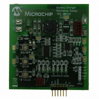
REFERENCE DESIGN MCP1631HV
Manufacturer
Microchip Technology
Datasheets
1.MCP1631VHVT-330EST.pdf
(34 pages)
2.MCP1631HV-330EST.pdf
(54 pages)
3.MCP1631RD-MCC2.pdf
(20 pages)
4.MCP1631RD-MCC2.pdf
(328 pages)
Specifications of MCP1631RD-MCC2
Main Purpose
Power Management, Battery Charger
Embedded
Yes, MCU, 8-Bit
Utilized Ic / Part
MCP1631HV, PIC16F883
Primary Attributes
1 ~ 2 Cell- Li-Ion, 1 ~ 5 Cell- NiCd/NiMH, 1 ~ 2 1W LEDs
Secondary Attributes
Status LEDs
Silicon Manufacturer
Microchip
Application Sub Type
Battery Charger
Kit Application Type
Power Management - Battery
Silicon Core Number
MCP1631HV, PIC16F883
Kit Contents
Board
Lead Free Status / RoHS Status
Lead free / RoHS Compliant
Lead Free Status / RoHS Status
Lead free / RoHS Compliant


© 2009 Microchip Technology Inc.
24. Press and hold the “ON/OFF” button on the charger board until the LED’s flash
25. Press and release the “CHEM” button until the “Li-Ion” LED is on.
26. Press and release the “# CELLS” button until the “0” display LED is on and the
27. Press and hold the “# CELLS” button on the charger board until the LED’s flash
28. Press the “ON/OFF” button. The charger will exit Configuration mode.
29. Turn off and disconnect the power supply.
30. Reconnect the variable supply (+) lead to the input connector (+) pin J1-1.
31. Reconnect the variable supply (-) lead to the input connector (-) pin J1-2.
32. Connect the Li-Ion battery pack to the charger board J2 connector.
33. Turn on the supply and set the voltage to 8.0V (any voltage between 6V and 12V
34. Press the “ON/OFF” button. The charger will start charging the battery.
35. Press the “CHEM” button to display the current charger state in HEX. “0” LED is
36. Press the “# CELLS” button to display the termination cause. No LED means no
37. Using an oscilloscope, refer to A.2 “Board – Schematic” and A.3 “Board – Top
38. Press the “ON/OFF” button. The charger will stop charging the battery.
(about 5 seconds). The board is now in Configuration Mode.
“1,2,3” display LED’s are off.
(about 5 seconds). The board is now calibrated to use the 4.200V as the Li-Ion
battery voltage.
is good).
the LS Bit.
premature termination.
Silk Layer” and probe the following components:
- V
- PWM = TP4
- Oscillator = TP5
- VS
- Slope Compensation = TP7
- Temperature = TP8 (if used)
- FB = TP9
- Drain Voltage = TP10
- Output Voltage = TP11
REF
OUT
= TP3
= TP6
Software
DS51791A-page 41
Related parts for MCP1631RD-MCC2
Image
Part Number
Description
Manufacturer
Datasheet
Request
R

Part Number:
Description:
REFERENCE DESIGN FOR MCP1631HV
Manufacturer:
Microchip Technology
Datasheet:

Part Number:
Description:
REF DES BATT CHARG OR LED DRIVER
Manufacturer:
Microchip Technology
Datasheet:

Part Number:
Description:
Manufacturer:
Microchip Technology Inc.
Datasheet:
Part Number:
Description:
Manufacturer:
Microchip Technology Inc.
Datasheet:
Part Number:
Description:
Manufacturer:
Microchip Technology Inc.
Datasheet:
Part Number:
Description:
Manufacturer:
Microchip Technology Inc.
Datasheet:
Part Number:
Description:
Manufacturer:
Microchip Technology Inc.
Datasheet:
Part Number:
Description:
Manufacturer:
Microchip Technology Inc.
Datasheet:
Part Number:
Description:
Manufacturer:
Microchip Technology Inc.
Datasheet:
Part Number:
Description:
Manufacturer:
Microchip Technology Inc.
Datasheet: