MCP1631RD-MCC2 Microchip Technology, MCP1631RD-MCC2 Datasheet - Page 47
MCP1631RD-MCC2
Manufacturer Part Number
MCP1631RD-MCC2
Description
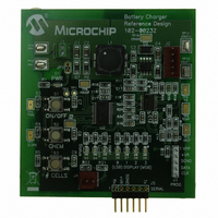
REFERENCE DESIGN MCP1631HV
Manufacturer
Microchip Technology
Datasheets
1.MCP1631VHVT-330EST.pdf
(34 pages)
2.MCP1631HV-330EST.pdf
(54 pages)
3.MCP1631RD-MCC2.pdf
(20 pages)
4.MCP1631RD-MCC2.pdf
(328 pages)
Specifications of MCP1631RD-MCC2
Main Purpose
Power Management, Battery Charger
Embedded
Yes, MCU, 8-Bit
Utilized Ic / Part
MCP1631HV, PIC16F883
Primary Attributes
1 ~ 2 Cell- Li-Ion, 1 ~ 5 Cell- NiCd/NiMH, 1 ~ 2 1W LEDs
Secondary Attributes
Status LEDs
Silicon Manufacturer
Microchip
Application Sub Type
Battery Charger
Kit Application Type
Power Management - Battery
Silicon Core Number
MCP1631HV, PIC16F883
Kit Contents
Board
Lead Free Status / RoHS Status
Lead free / RoHS Compliant
Lead Free Status / RoHS Status
Lead free / RoHS Compliant


© 2009 Microchip Technology Inc.
27. Press and release the “# CELLS” button until the “0” and “1” “Display” LED’s are
28. Press the “ON/OFF” button. The charger will exit Configuration mode.
29. Press the “ON/OFF” button. The charger will start charging the battery.
30. Press the “CHEM” button to display the current charger state in HEX. “0”
31. Press the “# CELLS” button to display the termination cause. No LED means no
32. Using an oscilloscope, refer to Appendices A.2 “Board – Schematic” and
33. Press the “ON/OFF” button. The charger will stop charging the battery.
on and the “2” and “3” “Display” LED’s are off. The LED display now displays “3”
in Hexadecimal.
“Display” LED is LS Bit.
premature termination.
A.3 “Board – Top Silk Layer” and probe the following components:
- V
- PWM = TP4
- Oscillator = TP5
- VS
- Slope Compensation = TP7
- Temperature = TP8
- FB = TP9
- Drain Voltage = TP10
- Output Voltage = TP11
REF
OUT
= TP3
= TP6
Software
DS51791A-page 43
Related parts for MCP1631RD-MCC2
Image
Part Number
Description
Manufacturer
Datasheet
Request
R

Part Number:
Description:
REFERENCE DESIGN FOR MCP1631HV
Manufacturer:
Microchip Technology
Datasheet:

Part Number:
Description:
REF DES BATT CHARG OR LED DRIVER
Manufacturer:
Microchip Technology
Datasheet:

Part Number:
Description:
Manufacturer:
Microchip Technology Inc.
Datasheet:
Part Number:
Description:
Manufacturer:
Microchip Technology Inc.
Datasheet:
Part Number:
Description:
Manufacturer:
Microchip Technology Inc.
Datasheet:
Part Number:
Description:
Manufacturer:
Microchip Technology Inc.
Datasheet:
Part Number:
Description:
Manufacturer:
Microchip Technology Inc.
Datasheet:
Part Number:
Description:
Manufacturer:
Microchip Technology Inc.
Datasheet:
Part Number:
Description:
Manufacturer:
Microchip Technology Inc.
Datasheet:
Part Number:
Description:
Manufacturer:
Microchip Technology Inc.
Datasheet: