MCP1631RD-MCC2 Microchip Technology, MCP1631RD-MCC2 Datasheet - Page 36
MCP1631RD-MCC2
Manufacturer Part Number
MCP1631RD-MCC2
Description
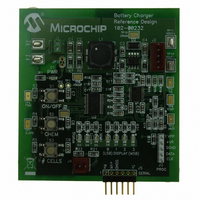
REFERENCE DESIGN MCP1631HV
Manufacturer
Microchip Technology
Datasheets
1.MCP1631VHVT-330EST.pdf
(34 pages)
2.MCP1631HV-330EST.pdf
(54 pages)
3.MCP1631RD-MCC2.pdf
(20 pages)
4.MCP1631RD-MCC2.pdf
(328 pages)
Specifications of MCP1631RD-MCC2
Main Purpose
Power Management, Battery Charger
Embedded
Yes, MCU, 8-Bit
Utilized Ic / Part
MCP1631HV, PIC16F883
Primary Attributes
1 ~ 2 Cell- Li-Ion, 1 ~ 5 Cell- NiCd/NiMH, 1 ~ 2 1W LEDs
Secondary Attributes
Status LEDs
Silicon Manufacturer
Microchip
Application Sub Type
Battery Charger
Kit Application Type
Power Management - Battery
Silicon Core Number
MCP1631HV, PIC16F883
Kit Contents
Board
Lead Free Status / RoHS Status
Lead free / RoHS Compliant
Lead Free Status / RoHS Status
Lead free / RoHS Compliant


PIC16F882/883/884/886/887
2.2.2.6
The PIR1 register contains the interrupt flag bits, as
shown in Register 2-6.
REGISTER 2-6:
DS41291F-page 34
bit 7
Legend:
R = Readable bit
-n = Value at POR
bit 7
bit 6
bit 5
bit 4
bit 3
bit 2
bit 1
bit 0
U-0
—
PIR1 Register
Unimplemented: Read as ‘0’
ADIF: A/D Converter Interrupt Flag bit
1 = A/D conversion complete (must be cleared in software)
0 = A/D conversion has not completed or has not been started
RCIF: EUSART Receive Interrupt Flag bit
1 = The EUSART receive buffer is full (cleared by reading RCREG)
0 = The EUSART receive buffer is not full
TXIF: EUSART Transmit Interrupt Flag bit
1 = The EUSART transmit buffer is empty (cleared by writing to TXREG)
0 = The EUSART transmit buffer is full
SSPIF: Master Synchronous Serial Port (MSSP) Interrupt Flag bit
1 = The MSSP interrupt condition has occurred, and must be cleared in software before returning from the
SPI
I
I
0 = No MSSP interrupt condition has occurred
CCP1IF: CCP1 Interrupt Flag bit
Capture mode:
1 = A TMR1 register capture occurred (must be cleared in software)
0 = No TMR1 register capture occurred
Compare mode:
1 = A TMR1 register compare match occurred (must be cleared in software)
0 = No TMR1 register compare match occurred
PWM mode:
Unused in this mode
TMR2IF: Timer2 to PR2 Interrupt Flag bit
1 = A Timer2 to PR2 match occurred (must be cleared in software)
0 = No Timer2 to PR2 match occurred
TMR1IF: Timer1 Overflow Interrupt Flag bit
1 = The TMR1 register overflowed (must be cleared in software)
0 = The TMR1 register did not overflow
2
2
C Slave/Master
C Master
R/W-0
ADIF
Interrupt Service Routine. The conditions that will set this bit are:
A transmission/reception has taken place
A transmission/reception has taken place
The initiated Start condition was completed by the MSSP module
The initiated Stop condition was completed by the MSSP module
The initiated restart condition was completed by the MSSP module
The initiated Acknowledge condition was completed by the MSSP module
A Start condition occurred while the MSSP module was idle (Multi-master system)
A Stop condition occurred while the MSSP module was idle (Multi-master system)
PIR1: PERIPHERAL INTERRUPT REQUEST REGISTER 1
W = Writable bit
‘1’ = Bit is set
RCIF
R-0
TXIF
R-0
U = Unimplemented bit, read as ‘0’
‘0’ = Bit is cleared
R/W-0
SSPIF
Note:
Interrupt flag bits are set when an interrupt
condition occurs, regardless of the state of
its corresponding enable bit or the Global
Enable bit, GIE of the INTCON register.
User
appropriate interrupt flag bits are clear prior
to enabling an interrupt.
CCP1IF
R/W-0
software
© 2009 Microchip Technology Inc.
x = Bit is unknown
TMR2IF
R/W-0
should
ensure
TMR1IF
R/W-0
bit 0
the
Related parts for MCP1631RD-MCC2
Image
Part Number
Description
Manufacturer
Datasheet
Request
R

Part Number:
Description:
REFERENCE DESIGN FOR MCP1631HV
Manufacturer:
Microchip Technology
Datasheet:

Part Number:
Description:
REF DES BATT CHARG OR LED DRIVER
Manufacturer:
Microchip Technology
Datasheet:

Part Number:
Description:
Manufacturer:
Microchip Technology Inc.
Datasheet:
Part Number:
Description:
Manufacturer:
Microchip Technology Inc.
Datasheet:
Part Number:
Description:
Manufacturer:
Microchip Technology Inc.
Datasheet:
Part Number:
Description:
Manufacturer:
Microchip Technology Inc.
Datasheet:
Part Number:
Description:
Manufacturer:
Microchip Technology Inc.
Datasheet:
Part Number:
Description:
Manufacturer:
Microchip Technology Inc.
Datasheet:
Part Number:
Description:
Manufacturer:
Microchip Technology Inc.
Datasheet:
Part Number:
Description:
Manufacturer:
Microchip Technology Inc.
Datasheet: