STEVAL-IPE009V1 STMicroelectronics, STEVAL-IPE009V1 Datasheet - Page 17
STEVAL-IPE009V1
Manufacturer Part Number
STEVAL-IPE009V1
Description
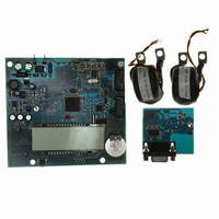
BOARD EVAL ST72321BR9/STPM14
Manufacturer
STMicroelectronics
Type
Other Power Managementr
Specifications of STEVAL-IPE009V1
Main Purpose
Power Management, Energy/Power Meter
Embedded
Yes, MCU, 8-Bit
Utilized Ic / Part
STPM14, ST72F321BR9T6
Primary Attributes
1-Ph 220 VAC, LCD Displays: No-Load, Reverse, Fraud, or Case Tampering
Secondary Attributes
Up to 4 Tariff Rates, Data Accumulated for Meter Life, Time Stamp for: Tamper, Fraud, Power Failure
Input Voltage
220 V
Product
Power Management Modules
Silicon Manufacturer
ST Micro
Silicon Core Number
ST72321BR9 And STPM14
Features
Continuously Detects, Displays No-Load Condition, Reverse Direction, Fraud And Case Tamper Condition
Lead Free Status / RoHS Status
Lead free / RoHS Compliant
For Use With/related Products
STPM14, ST72321BR9
Other names
497-8434
STEVAL-IPE009V1
STEVAL-IPE009V1


STPM11, STPM12, STPM13, STPM14
Figure 15. First order ∑ Δ A/D converter
7.4
A ∑ Δ modulator converts the input signal into a continuous serial stream of 1s and 0s at a
rate determined by the sampling clock. In the STPM1X, the sampling clock is equal to
f
output is subtracted from the input signal. If the loop gain is high enough, the average value
of the DAC output (and therefore the bit stream) can approach that of the input signal level.
When a large number of samples are averaged, a very precise value of the analog signal is
obtained. This averaging is carried out in the DSP section which implements decimation,
integration and DC offset cancellation of the supplied ∑ Δ signals. The gain of the
decimation filters is 1.004 for the voltage channel and 0.502 for the current channel. The
resulting signal has a resolution of 11bits for voltage channel and 16 bits for current channel.
Period and line voltage measurement
The period module measures the period of base frequency of voltage channel and checks if
the voltage signal frequency is in the band from f
produced at every positive peak of the line voltage. If the counted number of pulses between
two trailing edges of this signal is higher than the f
counting is stopped (internal signal is not available), it means that the base frequency is
lower than f
If the counted number of pulses within one line period is higher than the f
pulses, the base frequency exceeds the limit. In this case, such error must be repeated
three times in a row, in order to set the error flag BFR.
The BFR flag is also set if the value of the RMS voltage drops below a certain value (BFR-
on) and it is cleared when the RMS voltage goes above BFR-off threshold. The table below
shows the equivalent RMS voltage on the V
channel calibrator.
The BFR flag is also set if the RMS voltage across V
calculated with the following formula:
CLK
/4. The 1-bit DAC in the feedback loop is driven by the serial data stream. The DAC
Input analog signal
CLK
/2
17
Hz and an internal error flag BFR (base frequency range) is set.
+
Σ
-
Doc ID 13167 Rev 7
Integrator
∫
DAC
f
IP
CLK
/V
/4
IN
CLK
pins according to the value of the voltage
CLK
/2
IP
/2
17
-V
17
IN
Output digital signal
to f
Hz equivalent pulses or if the
drops below a threshold value
CLK
/2
15
. An internal signal is
Theory of operation
CLK
/2
15
equivalent
17/46
Related parts for STEVAL-IPE009V1
Image
Part Number
Description
Manufacturer
Datasheet
Request
R

Part Number:
Description:
BOARD DEMO TFT DISPLAY STR91
Manufacturer:
STMicroelectronics
Datasheet:

Part Number:
Description:
BOARD EVAL FOR MEMS SENSORS
Manufacturer:
STMicroelectronics
Datasheet:

Part Number:
Description:
KIT DEV STARTER ST10F276Z5
Manufacturer:
STMicroelectronics
Datasheet:

Part Number:
Description:
BOARD EVAL HDMI $ VIDEO SWITCH
Manufacturer:
STMicroelectronics
Datasheet:

Part Number:
Description:
BOARD DEMO ACCELEROMETER DIL24
Manufacturer:
STMicroelectronics
Datasheet:

Part Number:
Description:
BOARD STLM75/STDS75/ST72F651
Manufacturer:
STMicroelectronics
Datasheet:

Part Number:
Description:
EVAL BOARD 3AXIS MEMS ACCELLRMTR
Manufacturer:
STMicroelectronics
Datasheet:

Part Number:
Description:
BOARD EVAL 8BIT MICRO + TDE1708
Manufacturer:
STMicroelectronics
Datasheet:

Part Number:
Description:
EVAL BOARD A/D TS4657
Manufacturer:
STMicroelectronics
Datasheet:

Part Number:
Description:
BOARD ADAPTER 20DIP LIS3LV02DL
Manufacturer:
STMicroelectronics
Datasheet:
Part Number:
Description:
STMicroelectronics [RIPPLE-CARRY BINARY COUNTER/DIVIDERS]
Manufacturer:
STMicroelectronics
Datasheet:
Part Number:
Description:
STMicroelectronics [LIQUID-CRYSTAL DISPLAY DRIVERS]
Manufacturer:
STMicroelectronics
Datasheet:
Part Number:
Description:
BOARD EVAL FOR MEMS SENSORS
Manufacturer:
STMicroelectronics
Datasheet: