STEVAL-IPE009V1 STMicroelectronics, STEVAL-IPE009V1 Datasheet - Page 33
STEVAL-IPE009V1
Manufacturer Part Number
STEVAL-IPE009V1
Description
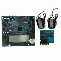
BOARD EVAL ST72321BR9/STPM14
Manufacturer
STMicroelectronics
Type
Other Power Managementr
Specifications of STEVAL-IPE009V1
Main Purpose
Power Management, Energy/Power Meter
Embedded
Yes, MCU, 8-Bit
Utilized Ic / Part
STPM14, ST72F321BR9T6
Primary Attributes
1-Ph 220 VAC, LCD Displays: No-Load, Reverse, Fraud, or Case Tampering
Secondary Attributes
Up to 4 Tariff Rates, Data Accumulated for Meter Life, Time Stamp for: Tamper, Fraud, Power Failure
Input Voltage
220 V
Product
Power Management Modules
Silicon Manufacturer
ST Micro
Silicon Core Number
ST72321BR9 And STPM14
Features
Continuously Detects, Displays No-Load Condition, Reverse Direction, Fraud And Case Tamper Condition
Lead Free Status / RoHS Status
Lead free / RoHS Compliant
For Use With/related Products
STPM14, ST72321BR9
Other names
497-8434
STEVAL-IPE009V1
STEVAL-IPE009V1


STPM11, STPM12, STPM13, STPM14
Permanent writing of the CFG bits
In order to make a permanent set of some CFG bits, use the following procedure:
For steps of set or clear, apply the timing shown in
SDA-TD.
In order to create a permanent set of the TSTD bit, which does not result in any more writing
to the Configuration bits, the procedure above must be conducted in such a way that steps 6
to 13 are performed in series during a single period of active SCS. The idle state of SCS
would make the signal TSTD immediately effective which in turn, would abort the procedure
and possibly destroy the device due to clearing of system signal RD. This would result in the
connecting of all gates of 3 V NMOS sense amplifiers of already permanently set CFG bits
to the V
1. collect all addresses of CFG bits to be permanently set into a list;
2. clear all OTP shadow latches;
3. set the system signal RD;
4. connect a current source of at least +14 V, 1 mA to 3 mA to VOTP;
5. wait for VOTP voltage to be stable;
6. set one OTP shadow latch from the list;
7. set the system signal WE;
8. wait for 300 s;
9. clear the system signal WE;
10. clear the OTP shadow latch which was set in step 6;
11. until all CFG bits are permanently set as desired, repeat steps 5 to 11;
12. disconnect the current source;
13. wait for VOTP voltage to be less than 3 V;
14. clear the system signal RD;
15. verify the correct writing, testing STPM1x operation;
16. if the verification of CFG bits fails, repeat steps 1 to 16.
OTP
source.
Doc ID 13167 Rev 7
Figure 21
- with proper signal on the
Theory of operation
33/46
Related parts for STEVAL-IPE009V1
Image
Part Number
Description
Manufacturer
Datasheet
Request
R

Part Number:
Description:
BOARD DEMO TFT DISPLAY STR91
Manufacturer:
STMicroelectronics
Datasheet:

Part Number:
Description:
BOARD EVAL FOR MEMS SENSORS
Manufacturer:
STMicroelectronics
Datasheet:

Part Number:
Description:
KIT DEV STARTER ST10F276Z5
Manufacturer:
STMicroelectronics
Datasheet:

Part Number:
Description:
BOARD EVAL HDMI $ VIDEO SWITCH
Manufacturer:
STMicroelectronics
Datasheet:

Part Number:
Description:
BOARD DEMO ACCELEROMETER DIL24
Manufacturer:
STMicroelectronics
Datasheet:

Part Number:
Description:
BOARD STLM75/STDS75/ST72F651
Manufacturer:
STMicroelectronics
Datasheet:

Part Number:
Description:
EVAL BOARD 3AXIS MEMS ACCELLRMTR
Manufacturer:
STMicroelectronics
Datasheet:

Part Number:
Description:
BOARD EVAL 8BIT MICRO + TDE1708
Manufacturer:
STMicroelectronics
Datasheet:

Part Number:
Description:
EVAL BOARD A/D TS4657
Manufacturer:
STMicroelectronics
Datasheet:

Part Number:
Description:
BOARD ADAPTER 20DIP LIS3LV02DL
Manufacturer:
STMicroelectronics
Datasheet:
Part Number:
Description:
STMicroelectronics [RIPPLE-CARRY BINARY COUNTER/DIVIDERS]
Manufacturer:
STMicroelectronics
Datasheet:
Part Number:
Description:
STMicroelectronics [LIQUID-CRYSTAL DISPLAY DRIVERS]
Manufacturer:
STMicroelectronics
Datasheet:
Part Number:
Description:
BOARD EVAL FOR MEMS SENSORS
Manufacturer:
STMicroelectronics
Datasheet: