STEVAL-IPE009V1 STMicroelectronics, STEVAL-IPE009V1 Datasheet - Page 25
STEVAL-IPE009V1
Manufacturer Part Number
STEVAL-IPE009V1
Description
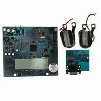
BOARD EVAL ST72321BR9/STPM14
Manufacturer
STMicroelectronics
Type
Other Power Managementr
Specifications of STEVAL-IPE009V1
Main Purpose
Power Management, Energy/Power Meter
Embedded
Yes, MCU, 8-Bit
Utilized Ic / Part
STPM14, ST72F321BR9T6
Primary Attributes
1-Ph 220 VAC, LCD Displays: No-Load, Reverse, Fraud, or Case Tampering
Secondary Attributes
Up to 4 Tariff Rates, Data Accumulated for Meter Life, Time Stamp for: Tamper, Fraud, Power Failure
Input Voltage
220 V
Product
Power Management Modules
Silicon Manufacturer
ST Micro
Silicon Core Number
ST72321BR9 And STPM14
Features
Continuously Detects, Displays No-Load Condition, Reverse Direction, Fraud And Case Tamper Condition
Lead Free Status / RoHS Status
Lead free / RoHS Compliant
For Use With/related Products
STPM14, ST72321BR9
Other names
497-8434
STEVAL-IPE009V1
STEVAL-IPE009V1


STPM11, STPM12, STPM13, STPM14
Table 13.
7.14
Table 14.
LVS (1 Bit)
KMOT (2 Bits)
0
0
0
0
1
1
1
1
Different settings for led signal
Due to the innovative and proprietary power calculation algorithm, the frequency signal is
not affected by any ripple at twice the line frequency. This feature strongly reduces the
calibration time of the meter.
Driving a stepper motor
The STPM1x is able to directly drive a stepper motor. An internal divider (mono-flop and
decoder) generates stepper driving signals MA and MB from signal AW. The MA and MB
signals are brought to the MOP and MON pins that are able to drive the stepper motor.
Several kinds of selections are possible for the driving signals according to the configuration
bits LVS and KMOT.
The numbers of pulses per kWh (PM) in the MOP and MON outputs are linked with the
number of pulses of the LED P (see previous paragraph - 7.13) pin with the following
relationship.
Configuration of MOP and MON pins
The mono-flop limits the length of the pulses according to the LVS bit value.
The decoder distributes the pulses to MA and MB alternatively, which means that each of
them has only one half of selected frequency.
Negative power is computed with its own sign, and the MOP and MON signals invert their
logic state in order to make the backward rotation direction of the motor. See the diagram
below.
0
1
2
3
KMOT (2 Bits)
0
1
2
3
0
1
2
3
Doc ID 13167 Rev 7
APL=0
Pulses
P
Pulses length
156.25 ms
156.25 ms
156.25 ms
156.25 ms
31.25 ms
31.25 ms
31.25 ms
31.25 ms
Theory of operation
Pulses
APL=1
P/128
P/256
P/64
P/32
P/1280
P/2560
P/128
P/256
P/640
P/320
P/64
P/32
PM
25/46
Related parts for STEVAL-IPE009V1
Image
Part Number
Description
Manufacturer
Datasheet
Request
R

Part Number:
Description:
BOARD DEMO TFT DISPLAY STR91
Manufacturer:
STMicroelectronics
Datasheet:

Part Number:
Description:
BOARD EVAL FOR MEMS SENSORS
Manufacturer:
STMicroelectronics
Datasheet:

Part Number:
Description:
KIT DEV STARTER ST10F276Z5
Manufacturer:
STMicroelectronics
Datasheet:

Part Number:
Description:
BOARD EVAL HDMI $ VIDEO SWITCH
Manufacturer:
STMicroelectronics
Datasheet:

Part Number:
Description:
BOARD DEMO ACCELEROMETER DIL24
Manufacturer:
STMicroelectronics
Datasheet:

Part Number:
Description:
BOARD STLM75/STDS75/ST72F651
Manufacturer:
STMicroelectronics
Datasheet:

Part Number:
Description:
EVAL BOARD 3AXIS MEMS ACCELLRMTR
Manufacturer:
STMicroelectronics
Datasheet:

Part Number:
Description:
BOARD EVAL 8BIT MICRO + TDE1708
Manufacturer:
STMicroelectronics
Datasheet:

Part Number:
Description:
EVAL BOARD A/D TS4657
Manufacturer:
STMicroelectronics
Datasheet:

Part Number:
Description:
BOARD ADAPTER 20DIP LIS3LV02DL
Manufacturer:
STMicroelectronics
Datasheet:
Part Number:
Description:
STMicroelectronics [RIPPLE-CARRY BINARY COUNTER/DIVIDERS]
Manufacturer:
STMicroelectronics
Datasheet:
Part Number:
Description:
STMicroelectronics [LIQUID-CRYSTAL DISPLAY DRIVERS]
Manufacturer:
STMicroelectronics
Datasheet:
Part Number:
Description:
BOARD EVAL FOR MEMS SENSORS
Manufacturer:
STMicroelectronics
Datasheet: