NCP1605FORWGEVB ON Semiconductor, NCP1605FORWGEVB Datasheet - Page 12
NCP1605FORWGEVB
Manufacturer Part Number
NCP1605FORWGEVB
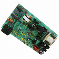
Description
EVAL BOARD FOR NCP1605FORWG
Manufacturer
ON Semiconductor
Datasheets
1.NCP1217P100G.pdf
(19 pages)
2.NCP1605ADR2G.pdf
(32 pages)
3.NCP1605FORWGEVB.pdf
(2 pages)
4.NCP1605FORWGEVB.pdf
(20 pages)
Specifications of NCP1605FORWGEVB
Design Resources
NCP1605FORWGEVB BOM NCP1605FORWGEVB Gerber Files NCP1605 EVB Schematic
Main Purpose
AC/DC, Primary and Secondary Side with PFC
Outputs And Type
1, Isolated
Voltage - Output
19V
Current - Output
8A
Voltage - Input
90 ~ 265VAC
Regulator Topology
Forward Converter
Frequency - Switching
133kHz
Board Type
Fully Populated
Utilized Ic / Part
NCP1217, NCP1605
Lead Free Status / RoHS Status
Lead free / RoHS Compliant
Power - Output
-
Lead Free Status / Rohs Status
Lead free / RoHS Compliant
For Use With/related Products
NCP1605FORWG
Other names
NCP1605FORWGEVBOS


Figure 22. Inserting a Resistor in Series with the Current
a duty cycle max at 74%. Over a 65 kHz frequency, for
instance, it corresponds to a 254 mV/ms ramp. In our
FLYBACK design, let’s suppose that our primary
inductance Lp is 350 mH, delivering 12 V with a Np:Ns ratio
of 1:0.1. The OFF time primary current slope is thus given
by:
projected over an Rsense of 0.1 Ω, for instance. If we select
75% of the downslope as the required amount of ramp
compensation, then we shall inject 27 mV/ms. Our
internal compensation being of 254 mV/ms, the divider
ratio (divratio) between Rcomp and the 19 kΩ is 0.106.
A
19 k · divratio
(1--divratio)
In the NCP1217, the ramp features a swing of 2.9 V with
Sense Information Brings Ramp Compensation
few
(Vout + Vf) ·
+
--
Setpoint
From
lines
Lp
= 2.26 kΩ
L.E.B.
of
Duty Cycle Typ = 74%
Np
Ns
= 371 mA∕ms
algebra
.
19 k
CS
2.9 V
0 V
to
Rcomp
or
determine
37 mV∕ms
Rsense
Rcomp:
http://onsemi.com
when
12
Latching Off the NCP1217
through a simple PNP bipolar transistor as depicted by
Figure 23. When OFF, Q1 is transparent to the operation.
When forward biased, the transistor pulls the Adj pin toward
V
above the latching level (typical 3.1 V). Figure 23 shows
how to wire the bipolar transistor to activate the latchoff. A
typical candidate for Q1 could be an MMBT3906 from
ON Semiconductor.
CC
Total latched shutdown can easily be implemented
Off
Figure 23. A Simple Bipolar Transistor Totally
and permanently latches- -off the IC as soon Vadj goes
Disables the IC
Q1
Rlimit
1
2
3
4
V
CC
8
7
6
5
CV
CC
Related parts for NCP1605FORWGEVB
Image
Part Number
Description
Manufacturer
Datasheet
Request
R

Part Number:
Description:
ON Semiconductor [VOLTAGE REGULATOR]
Manufacturer:
ON Semiconductor
Datasheet:
Part Number:
Description:
357-036-542-201 CARDEDGE 36POS DL .156 BLK LOPRO
Manufacturer:
ON Semiconductor
Datasheet:
Part Number:
Description:
357-036-542-201 CARDEDGE 36POS DL .156 BLK LOPRO
Manufacturer:
ON Semiconductor
Datasheet:
Part Number:
Description:
357-036-542-201 CARDEDGE 36POS DL .156 BLK LOPRO
Manufacturer:
ON Semiconductor
Datasheet:
Part Number:
Description:
357-036-542-201 CARDEDGE 36POS DL .156 BLK LOPRO
Manufacturer:
ON Semiconductor
Datasheet:
Part Number:
Description:
357-036-542-201 CARDEDGE 36POS DL .156 BLK LOPRO
Manufacturer:
ON Semiconductor
Datasheet:
Part Number:
Description:
357-036-542-201 CARDEDGE 36POS DL .156 BLK LOPRO
Manufacturer:
ON Semiconductor
Datasheet:
Part Number:
Description:
357-036-542-201 CARDEDGE 36POS DL .156 BLK LOPRO
Manufacturer:
ON Semiconductor
Datasheet:
Part Number:
Description:
357-036-542-201 CARDEDGE 36POS DL .156 BLK LOPRO
Manufacturer:
ON Semiconductor
Datasheet:
Part Number:
Description:
357-036-542-201 CARDEDGE 36POS DL .156 BLK LOPRO
Manufacturer:
ON Semiconductor
Datasheet:
Part Number:
Description:
357-036-542-201 CARDEDGE 36POS DL .156 BLK LOPRO
Manufacturer:
ON Semiconductor
Datasheet:
Part Number:
Description:
Manufacturer:
ON Semiconductor
Datasheet:
Part Number:
Description:
Manufacturer:
ON Semiconductor
Datasheet:
Part Number:
Description:
Manufacturer:
ON Semiconductor
Datasheet: