STEVAL-ILL008V1 STMicroelectronics, STEVAL-ILL008V1 Datasheet - Page 5
STEVAL-ILL008V1
Manufacturer Part Number
STEVAL-ILL008V1
Description
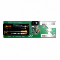
EVAL BOARD CREE LED FLASHLIGHT
Manufacturer
STMicroelectronics
Datasheets
1.L6920DC.pdf
(13 pages)
2.STEVAL-ILL008V1.pdf
(4 pages)
3.STEVAL-ILL008V1.pdf
(15 pages)
Specifications of STEVAL-ILL008V1
Mfg Application Notes
Low Voltage LED Driver AppNote
Design Resources
STEVAL-ILL008V1 Gerber Files STEVAL-ILL008V1 Schematic STEVAL-ILL008V1 Bill of Materials
Outputs And Type
1, Non-Isolated
Voltage - Output
3.5V
Features
1V Start up Input Voltage
Voltage - Input
1 ~ 5.5 V
Utilized Ic / Part
L6920
Product
Display Modules
Core Chip
L6920DA
Output Voltage
3.5V
Kit Contents
L6920D, L4971, L6902D Reference Board
Development Tool Type
Hardware - Eval/Demo Board
Tool / Board Applications
LED Flashlight
Mcu Supported Families
L6920DA
Lead Free Status / RoHS Status
Lead free / RoHS Compliant
Current - Output / Channel
-
Lead Free Status / Rohs Status
Details
Other names
497-5516


3
The L6920 is a high efficiency, low voltage step-up DC/DC converter particularly suitable for 1 to 3 cells (Li-Ion/
polymer, NiMH respectively) battery up conversion.
These performances are achieved via a strong reduction of quiescent current (10µA only) and adopting a syn-
chronous rectification, that implies also a reduced cost in the application (no external diode required).
Operation is based on maximum ON time - minimum OFF time control, tailored by a current limit set to 1A. A
simplified block diagram is shown here below.
Figure 6. Simplified Block Diagram
4
In L6920 the control is based on a comparator that continuously checks the status of output voltage.
If the output voltage is lower than the expected value, the control function of the L6920 directs the energy stored
in the inductor to be transferred to the load. This is accomplished by alternating between two basic steps:
- TON phase: the energy is transferred from the battery to the inductor by shorting LX node to ground via the N-
- TOFF phase: the energy stored in the inductor is transferred to the load through the synchronous switch for at
So, in case of light load, the device works in PFM mode, as shown in figures 7 to 10.
channel power switch. The switch is turned off if the current flowing in the inductor reaches 1A or after a max-
imum on time set to 5µs.
least a minimum off time equal to 1µs. After this, the synchronous switch is turned off as soon as the output
voltage goes lower than the regulated voltage or the current flowing in the inductor goes down to zero.
Detailed Description
Principle of Operation
SHDN
V
LBO
REF
C
A
B
-
+
-
+
Y
VBG
V
GND
R
Toff min
FB
1µsec
VBG
OUT
1
VBG
,R
+
-
2
OPAMP
LBI
Y
A
B
C
(CR)
Q
S
ZERO CROSSING
R
Ton max
5µsec
-
+
CURRENT LIMIT
- +
-
+
VOUT
D99IN1041
OUT
LX
GND
FB
V
IN
V
OUT
L6920
5/13
Related parts for STEVAL-ILL008V1
Image
Part Number
Description
Manufacturer
Datasheet
Request
R

Part Number:
Description:
BOARD EVAL FOR MEMS SENSORS
Manufacturer:
STMicroelectronics
Datasheet:

Part Number:
Description:
KIT DEV STARTER ST10F276Z5
Manufacturer:
STMicroelectronics
Datasheet:

Part Number:
Description:
BOARD EVAL HDMI $ VIDEO SWITCH
Manufacturer:
STMicroelectronics
Datasheet:

Part Number:
Description:
BOARD DEMO ACCELEROMETER DIL24
Manufacturer:
STMicroelectronics
Datasheet:

Part Number:
Description:
BOARD STLM75/STDS75/ST72F651
Manufacturer:
STMicroelectronics
Datasheet:

Part Number:
Description:
EVAL BOARD 3AXIS MEMS ACCELLRMTR
Manufacturer:
STMicroelectronics
Datasheet:

Part Number:
Description:
BOARD EVAL 8BIT MICRO + TDE1708
Manufacturer:
STMicroelectronics
Datasheet:

Part Number:
Description:
EVAL BOARD A/D TS4657
Manufacturer:
STMicroelectronics
Datasheet:

Part Number:
Description:
BOARD ADAPTER 20DIP LIS3LV02DL
Manufacturer:
STMicroelectronics
Datasheet:

Part Number:
Description:
BOARD DEMO STM8S207R6/LIS331DLH
Manufacturer:
STMicroelectronics
Datasheet:

Part Number:
Description:
STMicroelectronics [RIPPLE-CARRY BINARY COUNTER/DIVIDERS]
Manufacturer:
STMicroelectronics
Datasheet:
Part Number:
Description:
STMicroelectronics [LIQUID-CRYSTAL DISPLAY DRIVERS]
Manufacturer:
STMicroelectronics
Datasheet:
Part Number:
Description:
BOARD EVAL FOR MEMS SENSORS
Manufacturer:
STMicroelectronics
Datasheet: