STEVAL-ILL008V1 STMicroelectronics, STEVAL-ILL008V1 Datasheet - Page 6
STEVAL-ILL008V1
Manufacturer Part Number
STEVAL-ILL008V1
Description
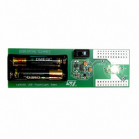
EVAL BOARD CREE LED FLASHLIGHT
Manufacturer
STMicroelectronics
Datasheets
1.L6920DC.pdf
(13 pages)
2.STEVAL-ILL008V1.pdf
(4 pages)
3.STEVAL-ILL008V1.pdf
(15 pages)
Specifications of STEVAL-ILL008V1
Mfg Application Notes
Low Voltage LED Driver AppNote
Design Resources
STEVAL-ILL008V1 Gerber Files STEVAL-ILL008V1 Schematic STEVAL-ILL008V1 Bill of Materials
Outputs And Type
1, Non-Isolated
Voltage - Output
3.5V
Features
1V Start up Input Voltage
Voltage - Input
1 ~ 5.5 V
Utilized Ic / Part
L6920
Product
Display Modules
Core Chip
L6920DA
Output Voltage
3.5V
Kit Contents
L6920D, L4971, L6902D Reference Board
Development Tool Type
Hardware - Eval/Demo Board
Tool / Board Applications
LED Flashlight
Mcu Supported Families
L6920DA
Lead Free Status / RoHS Status
Lead free / RoHS Compliant
Current - Output / Channel
-
Lead Free Status / Rohs Status
Details
Other names
497-5516


L6920
Figure 7. PFM mode Condition: V
Trace1: Vout (50mV~/div) Trace 4: IL (100mA/div)
Time div.: 5µs/div
Figure 8. Heavier load - Train pulses overlapping.
Trace1: V
Time div.: 10 µs/div
When Iload is heavier, the pulse trains are overlapped. Figures 7 - 8 show some possible behaviors.
Considering that current in the inductor is limited to 1A, the maximum load current is defined by the following
relationship:
Where η is the efficiency and I
Of course, if Iload is greater than Iload_lim the regulation is lost (figure 11).
6/13
out
(100mV~/div) Trace 4: I
I
load_lim
lim
=1A.
out
=
L
= 5V; V
(200mA/div)
---------- -
V
V
out
in
in
⋅
⎛
⎝
=1.5V.
I
lim
–
T
off min
Figure 9. Heavy load - Inductor current ripples
below I
(200mA/div) Time div.: 20 µs/div
Figure 10. Heavy load and High ESR. Regulation
falls in continuous mode of operation. Trace1:
V
div.: 5 µs/div
out
⋅
V
------------------------- -
(100mV~/div) Trace 4: I
out
2 L
lim
⋅
–
Trace1: V
V
in
⎞ η
⎠
⋅
eq. (1)
out
(100mV~/div) Trace 4: I
L
(200mA/div). Time
L
Related parts for STEVAL-ILL008V1
Image
Part Number
Description
Manufacturer
Datasheet
Request
R

Part Number:
Description:
BOARD EVAL FOR MEMS SENSORS
Manufacturer:
STMicroelectronics
Datasheet:

Part Number:
Description:
KIT DEV STARTER ST10F276Z5
Manufacturer:
STMicroelectronics
Datasheet:

Part Number:
Description:
BOARD EVAL HDMI $ VIDEO SWITCH
Manufacturer:
STMicroelectronics
Datasheet:

Part Number:
Description:
BOARD DEMO ACCELEROMETER DIL24
Manufacturer:
STMicroelectronics
Datasheet:

Part Number:
Description:
BOARD STLM75/STDS75/ST72F651
Manufacturer:
STMicroelectronics
Datasheet:

Part Number:
Description:
EVAL BOARD 3AXIS MEMS ACCELLRMTR
Manufacturer:
STMicroelectronics
Datasheet:

Part Number:
Description:
BOARD EVAL 8BIT MICRO + TDE1708
Manufacturer:
STMicroelectronics
Datasheet:

Part Number:
Description:
EVAL BOARD A/D TS4657
Manufacturer:
STMicroelectronics
Datasheet:

Part Number:
Description:
BOARD ADAPTER 20DIP LIS3LV02DL
Manufacturer:
STMicroelectronics
Datasheet:

Part Number:
Description:
BOARD DEMO STM8S207R6/LIS331DLH
Manufacturer:
STMicroelectronics
Datasheet:

Part Number:
Description:
STMicroelectronics [RIPPLE-CARRY BINARY COUNTER/DIVIDERS]
Manufacturer:
STMicroelectronics
Datasheet:
Part Number:
Description:
STMicroelectronics [LIQUID-CRYSTAL DISPLAY DRIVERS]
Manufacturer:
STMicroelectronics
Datasheet:
Part Number:
Description:
BOARD EVAL FOR MEMS SENSORS
Manufacturer:
STMicroelectronics
Datasheet: