STEVAL-ILL008V1 STMicroelectronics, STEVAL-ILL008V1 Datasheet - Page 7
STEVAL-ILL008V1
Manufacturer Part Number
STEVAL-ILL008V1
Description
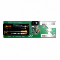
EVAL BOARD CREE LED FLASHLIGHT
Manufacturer
STMicroelectronics
Datasheets
1.L6920DC.pdf
(13 pages)
2.STEVAL-ILL008V1.pdf
(4 pages)
3.STEVAL-ILL008V1.pdf
(15 pages)
Specifications of STEVAL-ILL008V1
Mfg Application Notes
Low Voltage LED Driver AppNote
Design Resources
STEVAL-ILL008V1 Gerber Files STEVAL-ILL008V1 Schematic STEVAL-ILL008V1 Bill of Materials
Outputs And Type
1, Non-Isolated
Voltage - Output
3.5V
Features
1V Start up Input Voltage
Voltage - Input
1 ~ 5.5 V
Utilized Ic / Part
L6920
Product
Display Modules
Core Chip
L6920DA
Output Voltage
3.5V
Kit Contents
L6920D, L4971, L6902D Reference Board
Development Tool Type
Hardware - Eval/Demo Board
Tool / Board Applications
LED Flashlight
Mcu Supported Families
L6920DA
Lead Free Status / RoHS Status
Lead free / RoHS Compliant
Current - Output / Channel
-
Lead Free Status / Rohs Status
Details
Other names
497-5516


Figure 11. No regulation. I
Trace1: V
Time div.: 5 µs/div
4.1 Start-up
One of the key features of L6920 is the startup at sup-
ply voltage down to 1V (please see the diagram in
Figure 5. in case of heavy load).
The device leaves the startup mode of operation as
soon as VOUT goes over 1.4V. During startup, the
synchronous switch is off and the energy is trans-
ferred to the load through its intrinsic body diode.
The N-channel switches with a very low RDSon
thanks to an internal charge pump used to bias the
power mos gate. Because of this modified behavior,
TON/TOFF times are lengthened. Current limit and
zero crossing detection are still available.
4.2 Shutdown
In shutdown mode (SHDN pulled low) all internal cir-
cuitries are turned off, minimizing the current provid-
ed by the battery (I
Both switches are turned off, and the low battery
comparator output is forced in high impedance state.
out
(100mV~/div) Trace 4: I
SHDN
< 100 nA, in typical case).
load
> I
L
load_lim
(200mA/div).
The synchronous switch body diode causes a para-
sitic path between power supply and output that can't
be avoided also in shutdown.
4.3 Low battery detection
The L6920 includes a low battery detector compara-
tor. Threshold is VREF voltage and a 1.3% hystere-
sis is added to avoid oscillations when input crosses
the threshold slowly. The LBO is an open drain out-
put so a pull up resistor is required for a proper use.
4.4 Reverse polarity
A protection circuit has been implemented to avoid
that L6920 and the battery are destroyed in case of
wrong battery insertion.
In addition, this circuit has been designed so that the
current required by the battery is zero also in reverse
polarity.
5
5.1 Output voltage selection
Output voltage must be selected acting on FB pin.
Three choices are available: fixed 3.3V, 5V or adjust-
able output set via an external resistor divider.
Table 5. Output Voltage Selection
V
V
2V ≤ V
OUT
OUT
Application Information
= 3.3V
= 5V
OUT
≤ 5.2V
FB pin connected to OUT (see
application circuit)
FB pin connected to GND
FB pin connected to a resistive
divider
V
OUT
=
1.23V 1
⎛
⎝
+
R4
------- -
R5
⎞
⎠
L6920
7/13
Related parts for STEVAL-ILL008V1
Image
Part Number
Description
Manufacturer
Datasheet
Request
R

Part Number:
Description:
BOARD EVAL FOR MEMS SENSORS
Manufacturer:
STMicroelectronics
Datasheet:

Part Number:
Description:
KIT DEV STARTER ST10F276Z5
Manufacturer:
STMicroelectronics
Datasheet:

Part Number:
Description:
BOARD EVAL HDMI $ VIDEO SWITCH
Manufacturer:
STMicroelectronics
Datasheet:

Part Number:
Description:
BOARD DEMO ACCELEROMETER DIL24
Manufacturer:
STMicroelectronics
Datasheet:

Part Number:
Description:
BOARD STLM75/STDS75/ST72F651
Manufacturer:
STMicroelectronics
Datasheet:

Part Number:
Description:
EVAL BOARD 3AXIS MEMS ACCELLRMTR
Manufacturer:
STMicroelectronics
Datasheet:

Part Number:
Description:
BOARD EVAL 8BIT MICRO + TDE1708
Manufacturer:
STMicroelectronics
Datasheet:

Part Number:
Description:
EVAL BOARD A/D TS4657
Manufacturer:
STMicroelectronics
Datasheet:

Part Number:
Description:
BOARD ADAPTER 20DIP LIS3LV02DL
Manufacturer:
STMicroelectronics
Datasheet:

Part Number:
Description:
BOARD DEMO STM8S207R6/LIS331DLH
Manufacturer:
STMicroelectronics
Datasheet:

Part Number:
Description:
STMicroelectronics [RIPPLE-CARRY BINARY COUNTER/DIVIDERS]
Manufacturer:
STMicroelectronics
Datasheet:
Part Number:
Description:
STMicroelectronics [LIQUID-CRYSTAL DISPLAY DRIVERS]
Manufacturer:
STMicroelectronics
Datasheet:
Part Number:
Description:
BOARD EVAL FOR MEMS SENSORS
Manufacturer:
STMicroelectronics
Datasheet: