STEVAL-ILL008V1 STMicroelectronics, STEVAL-ILL008V1 Datasheet - Page 9
STEVAL-ILL008V1
Manufacturer Part Number
STEVAL-ILL008V1
Description
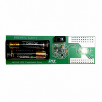
EVAL BOARD CREE LED FLASHLIGHT
Manufacturer
STMicroelectronics
Datasheets
1.L6920DC.pdf
(13 pages)
2.STEVAL-ILL008V1.pdf
(4 pages)
3.STEVAL-ILL008V1.pdf
(15 pages)
Specifications of STEVAL-ILL008V1
Mfg Application Notes
Low Voltage LED Driver AppNote
Design Resources
STEVAL-ILL008V1 Gerber Files STEVAL-ILL008V1 Schematic STEVAL-ILL008V1 Bill of Materials
Outputs And Type
1, Non-Isolated
Voltage - Output
3.5V
Features
1V Start up Input Voltage
Voltage - Input
1 ~ 5.5 V
Utilized Ic / Part
L6920
Product
Display Modules
Core Chip
L6920DA
Output Voltage
3.5V
Kit Contents
L6920D, L4971, L6902D Reference Board
Development Tool Type
Hardware - Eval/Demo Board
Tool / Board Applications
LED Flashlight
Mcu Supported Families
L6920DA
Lead Free Status / RoHS Status
Lead free / RoHS Compliant
Current - Output / Channel
-
Lead Free Status / Rohs Status
Details
Other names
497-5516


Table 7. Capacitors distributors main list
5.3 Inductor selection
Usually, inductors ranging between 5µH to 40µH satisfy most of the applications.
Small value inductors have smaller physical size and guarantee a faster response to load transient but in steady
state condition a bigger ripple on output voltage is generated. In fact the output ripple voltage is given by Ipeak
multiplied by ESR. Furthermore, as shown in equation (1), inductor size affects also the maximum current de-
liverable to the load. Lastly, a low series resistance is suggested if very high efficiency values are needed. Any-
way, the saturation current of the choke should be higher than the peak current limit of the device (1A).
Good surface mounting inductors are available from COILCRAFTS, COILTRONICS, MURATA and other souc-
es. In the following table are listed some suggested components.
Table 8. Inductors distributors main list
5.4 Layout Guidelines
The board layout is very important in order to minimize noise, high frequency resonance problems and electro-
magnetic interference.
It is essential to keep as small as possible the high switching current circulating paths to reduce radiation and
resonance problems. So, the output and input cap should be very close to the device.
The external resistor dividers, if used, should be as close as possible to the pins of the device (FB and LBI) and
as far as possible from the high current circulating paths, to avoid pick up noise.
Large traces for high current paths and an extended groundplane, help to reduce the noise and increase the
efficiency.
For an example of recommended layout see the following evaluation board.
AVX
KEMET
PANASONIC
SANYO POSCAP
SPRAGUE
Coilcraft
Coiltronics
BI
Murata
Panasonic
Sumida
Manufacturer
Manufacturer
DO1813HC
DO1608
UP1B
TP3
HM76-2
HM76-1
LQN6C
ELL6SH
ELL6RH
CR43
TPS
T510/T494/
T495
EEFCD
TPA/B/C
595D
Series
Series
22 to 33
4.7 to 15
22 to 33
4.7 to 15
22 to 33
4.7 to 10
10 to 22
10 to 22
5.1 to10
4.7 to 10
15 to 470
10 to 470
22 to 47
22 to 230
100 to 390
Cap Value (µF)
Inductor Value (uH)
6.3
6
6.3
6.3
6.3
Rated Voltage (V)
1 to 1.2
0.9 to 1.5
1 to 1.2
0.97 to 1.6
1 to 1.2
1 to 1.5
1.2 to 1.7
0.9 to 1.5
11 to 1.55
0.84 to 1.15
Saturation Current (A)
50 to 1500
30 to 1000
50 to 700
40 to 80
160 to 700
ESR (mΩ)
L6920
9/13
Related parts for STEVAL-ILL008V1
Image
Part Number
Description
Manufacturer
Datasheet
Request
R

Part Number:
Description:
BOARD EVAL FOR MEMS SENSORS
Manufacturer:
STMicroelectronics
Datasheet:

Part Number:
Description:
KIT DEV STARTER ST10F276Z5
Manufacturer:
STMicroelectronics
Datasheet:

Part Number:
Description:
BOARD EVAL HDMI $ VIDEO SWITCH
Manufacturer:
STMicroelectronics
Datasheet:

Part Number:
Description:
BOARD DEMO ACCELEROMETER DIL24
Manufacturer:
STMicroelectronics
Datasheet:

Part Number:
Description:
BOARD STLM75/STDS75/ST72F651
Manufacturer:
STMicroelectronics
Datasheet:

Part Number:
Description:
EVAL BOARD 3AXIS MEMS ACCELLRMTR
Manufacturer:
STMicroelectronics
Datasheet:

Part Number:
Description:
BOARD EVAL 8BIT MICRO + TDE1708
Manufacturer:
STMicroelectronics
Datasheet:

Part Number:
Description:
EVAL BOARD A/D TS4657
Manufacturer:
STMicroelectronics
Datasheet:

Part Number:
Description:
BOARD ADAPTER 20DIP LIS3LV02DL
Manufacturer:
STMicroelectronics
Datasheet:

Part Number:
Description:
BOARD DEMO STM8S207R6/LIS331DLH
Manufacturer:
STMicroelectronics
Datasheet:

Part Number:
Description:
STMicroelectronics [RIPPLE-CARRY BINARY COUNTER/DIVIDERS]
Manufacturer:
STMicroelectronics
Datasheet:
Part Number:
Description:
STMicroelectronics [LIQUID-CRYSTAL DISPLAY DRIVERS]
Manufacturer:
STMicroelectronics
Datasheet:
Part Number:
Description:
BOARD EVAL FOR MEMS SENSORS
Manufacturer:
STMicroelectronics
Datasheet: