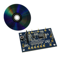
STEVAL-ILL021V1 STMicroelectronics, STEVAL-ILL021V1 Datasheet - Page 16

STEVAL-ILL021V1
Manufacturer Part Number
STEVAL-ILL021V1
Description
BOARD EVAL LCD BACKLIGHT LED7707
Manufacturer
STMicroelectronics
Specifications of STEVAL-ILL021V1
Design Resources
STEVAL-ILL021V1 Bill of Material STEVAL-ILL021V1 Schematic
Current - Output / Channel
85mA
Outputs And Type
6, Non-Isolated
Voltage - Output
36 V
Features
Dimmable, Extra 5V Output
Voltage - Input
4.5 ~ 36 V
Utilized Ic / Part
LED7707
Description/function
LCD backlight demonstration board
Operating Voltage
4.5 V to 36 V
Product
Display Modules
Core Chip
LED7707
No. Of Outputs
1
Output Voltage
36V
Dimming Control Type
PWM
Mcu Supported Families
LED7707
Lead Free Status / RoHS Status
Lead free by exemption / RoHS compliant by exemption
For Use With/related Products
LED7707
Other names
497-10044
Available stocks
Company
Part Number
Manufacturer
Quantity
Price
Company:
Part Number:
STEVAL-ILL021V1
Manufacturer:
STMicroelectronics
Quantity:
1
Operation description
5.1.6
16/47
Figure 11. External sync waveforms
Slope compensation
The constant frequency, peak current-mode topology has the advantage of very easy loop
compensation with output ceramic caps (reduced cost and size of the application) and fast
transient response. In addition, the intrinsic peak-current measurement simplifies the
current limit protection, avoiding undesired saturation of the inductor.
On the other side, this topology has a drawback: there is an inherent open loop instability
when operating with a duty-ratio greater than 0.5. This phenomenon is known as “Sub-
Harmonic Instability” and can be avoided by adding an external ramp to the one coming
from the sensed current. This compensating technique, based on the additional ramp, is
called “slope compensation”. In
the small perturbation ΔI
and the system reverts to a stable situation.
The SLOPE pin allows to properly set the amount of slope compensation connecting a
simple resistor R
starts at 35% (typ.) of each switching period and its slope is given by the following equation:
Equation 5
Where K
To avoid sub-harmonic instability, the compensating slope should be at least half the slope
of the inductor current during the off-phase when the duty-cycle is greater than 50%. The
value of R
Slave SYNC pin voltage
Slave LX pin voltage
FSW pin voltage (ext. sync)
S
SLOPE
= 5.8
⋅
can be calculated according to equation 6.
SLOPE
10
10
s
-1
between the SLOPE pin and the output. The compensation ramp
L
, V
dies away in subsequent cycles thanks to the slope compensation
BE
= 2 V (typ.) and S
270mV threshold
Figure 12
S
E
=
K
S
⎛
⎜
⎜
⎝
, where the switching duty-cycle is higher than 0.5,
V
OUT
R
−
SLOPE
E
V
is the slope ramp in [A/s].
IN
270ns minimum
−
V
BE
⎞
⎟
⎟
⎠
LED7707
AM00588v1


