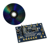
STEVAL-ILL021V1 STMicroelectronics, STEVAL-ILL021V1 Datasheet - Page 36

STEVAL-ILL021V1
Manufacturer Part Number
STEVAL-ILL021V1
Description
BOARD EVAL LCD BACKLIGHT LED7707
Manufacturer
STMicroelectronics
Specifications of STEVAL-ILL021V1
Design Resources
STEVAL-ILL021V1 Bill of Material STEVAL-ILL021V1 Schematic
Current - Output / Channel
85mA
Outputs And Type
6, Non-Isolated
Voltage - Output
36 V
Features
Dimmable, Extra 5V Output
Voltage - Input
4.5 ~ 36 V
Utilized Ic / Part
LED7707
Description/function
LCD backlight demonstration board
Operating Voltage
4.5 V to 36 V
Product
Display Modules
Core Chip
LED7707
No. Of Outputs
1
Output Voltage
36V
Dimming Control Type
PWM
Mcu Supported Families
LED7707
Lead Free Status / RoHS Status
Lead free by exemption / RoHS compliant by exemption
For Use With/related Products
LED7707
Other names
497-10044
Available stocks
Company
Part Number
Manufacturer
Quantity
Price
Company:
Part Number:
STEVAL-ILL021V1
Manufacturer:
STMicroelectronics
Quantity:
1
Application information
6.4.9
36/47
Power dissipation estimate
As explained in section 5.2, there are several contributions to the total power dissipation.
Neglecting the power dissipated by the LDO (surely less significant compared with the other
contributions), equation (18), (20), (21) and (22) help to estimate the overall power
dissipation.
Before starting the power dissipation estimate it is important to highlight that the following
calculations are considering the worst case (the actual value of the dissipated power would
require measurements). Therefore the power dissipation is estimated according to the
following assumptions:
1.
2.
3.
4.
The conduction and switching losses on the internal power switch can be calculated as:
Equation 41
Equation 42
where t
The power dissipation related to the current generators is given by:
Equation 43
Equation 44
Equation 45
The junction temperature can be estimated by equation (18) considering T
Equation 46
Minimum input voltage (10.8 V), which leads to maximum input current (and also D will
have the higher value, see
Maximum R
LEDs in the row of the leading generator will have the maximum forward voltage,
whereas all other LEDs in the other rows will have the minimum forward voltage.
100 % dimming signal duty cycle is considered.
r
= t
f
= 15 ns
P
GEN
DS(on)
=
P
I
ROW
, D
P
of the internal power MOSFET;
tot
, D
sw
⋅
≅
P
P
(
n
, D
GEN
P
=
ROWs
, D
cond
T
V
cond
,
J
Section 6.4.4
Master
OUT
=
=
−
T
+
R
⋅
1
Amb
I
P
)
IN
DSon
=
⋅
, D
(
I
⋅
V
sw
ROW
+
f
sw
IFB
R
⋅
+
I
IN
2
⋅
th
P
+
⋅
t (
);
,
GEN
⋅
V
JA
Δ
r
D
IFB
V
+
2
⋅
⋅
, f
,
P
Master
D
) t
LEDs
⋅
, D
f
D
DIM
tot
⋅
DIM
D
⋅
=
=
DIM
+
n
=
LEDs
72
P
216
GEN
42
=
°
C
mW
233
mW
)
⋅
=
D
. 1
DIM
mW
12
=
W
630
mW
A
= 25 °C:
LED7707


