STEVAL-ILL021V1 STMicroelectronics, STEVAL-ILL021V1 Datasheet - Page 25
STEVAL-ILL021V1
Manufacturer Part Number
STEVAL-ILL021V1
Description
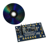
BOARD EVAL LCD BACKLIGHT LED7707
Manufacturer
STMicroelectronics
Specifications of STEVAL-ILL021V1
Design Resources
STEVAL-ILL021V1 Bill of Material STEVAL-ILL021V1 Schematic
Current - Output / Channel
85mA
Outputs And Type
6, Non-Isolated
Voltage - Output
36 V
Features
Dimmable, Extra 5V Output
Voltage - Input
4.5 ~ 36 V
Utilized Ic / Part
LED7707
Description/function
LCD backlight demonstration board
Operating Voltage
4.5 V to 36 V
Product
Display Modules
Core Chip
LED7707
No. Of Outputs
1
Output Voltage
36V
Dimming Control Type
PWM
Mcu Supported Families
LED7707
Lead Free Status / RoHS Status
Lead free by exemption / RoHS compliant by exemption
For Use With/related Products
LED7707
Other names
497-10044
Available stocks
Company
Part Number
Manufacturer
Quantity
Price
Company:

Part Number:
STEVAL-ILL021V1
Manufacturer:
STMicroelectronics
Quantity:
1


LED7707
6
6.1
6.1.1
Application information
System stability
The boost section of the LED7707 is a fixed frequency, current-mode converter. During
normal operation, a minimum voltage selection circuit compares all the voltage drops across
the active current generators and provides the minimum one to the error amplifier. The
output voltage of the error amplifier determines the inductor peak current in order to keep its
inverting input equal to the reference voltage (700 mV typ). The compensation network
consists of a simple RC series (R
The calculation of R
dynamic performance of the boost converter and is strictly related to the operating
conditions.
Loop compensation
The compensation network can be quickly calculated using equations 11 to 16. Once both
R
get the optimal dynamic performance from the application.
The first parameter to be fixed is the switching frequency. Normally, a high switching
frequency allows reducing the size of the inductor and positively affects the dynamic
response of the converter (wider bandwidth) but increases the switching losses. For most of
applications, the fixed value (660 kHz) represents a good trade-off between power
dissipation and dynamic response, allowing to save an external resistor at the same time. In
low-profile applications, the inductor value is often kept low to reduce the number of turns;
an inductor value in the 4.7 µH-15 µH range is a good starting choice.
In order to avoid instability due to interaction between the DC-DC converter's loop and the
current generators' loop, the bandwidth of the boost should not exceed the bandwidth of the
current generators. A unity-gain frequency (f
take care not to exceed the CCM-mode right half-plane zero (RHPZ).
Equation 11
Equation 12
Equation 13 a
COMP
and C
COMP
have been determined, a fine-tuning phase may be required in order to
COMP
and C
f
U
≤
0
2 .
COMP
COMP
⋅
2
M
⋅ π
2
is fundamental to achieve optimal loop stability and
R
L
- C
f
U
M =
=
≤
COMP
0
0
U
2 .
V
2 .
) in the order of 30-40 kHz is acceptable. Also,
V
IN
⋅
OUT
⋅
⎛
⎜
⎜
⎝
,
) between the COMP pin and ground.
F
min
V
V
SW
IN
OUT
,
min
2
⋅ π
⎞
⎟
⎟
⎠
2
⎛
⎜
⎜
⎝
L
V
I
OUT
OUT
⎞
⎟
⎟
⎠
Application information
25/47
Related parts for STEVAL-ILL021V1
Image
Part Number
Description
Manufacturer
Datasheet
Request
R

Part Number:
Description:
BOARD EVAL FOR MEMS SENSORS
Manufacturer:
STMicroelectronics
Datasheet:

Part Number:
Description:
KIT DEV STARTER ST10F276Z5
Manufacturer:
STMicroelectronics
Datasheet:

Part Number:
Description:
BOARD EVAL HDMI $ VIDEO SWITCH
Manufacturer:
STMicroelectronics
Datasheet:

Part Number:
Description:
BOARD DEMO ACCELEROMETER DIL24
Manufacturer:
STMicroelectronics
Datasheet:

Part Number:
Description:
BOARD STLM75/STDS75/ST72F651
Manufacturer:
STMicroelectronics
Datasheet:

Part Number:
Description:
EVAL BOARD 3AXIS MEMS ACCELLRMTR
Manufacturer:
STMicroelectronics
Datasheet:

Part Number:
Description:
BOARD EVAL 8BIT MICRO + TDE1708
Manufacturer:
STMicroelectronics
Datasheet:

Part Number:
Description:
EVAL BOARD A/D TS4657
Manufacturer:
STMicroelectronics
Datasheet:

Part Number:
Description:
BOARD ADAPTER 20DIP LIS3LV02DL
Manufacturer:
STMicroelectronics
Datasheet:

Part Number:
Description:
BOARD DEMO STM8S207R6/LIS331DLH
Manufacturer:
STMicroelectronics
Datasheet:

Part Number:
Description:
STMicroelectronics [RIPPLE-CARRY BINARY COUNTER/DIVIDERS]
Manufacturer:
STMicroelectronics
Datasheet:
Part Number:
Description:
STMicroelectronics [LIQUID-CRYSTAL DISPLAY DRIVERS]
Manufacturer:
STMicroelectronics
Datasheet:
Part Number:
Description:
BOARD EVAL FOR MEMS SENSORS
Manufacturer:
STMicroelectronics
Datasheet: