STEVAL-ILL021V1 STMicroelectronics, STEVAL-ILL021V1 Datasheet - Page 19
STEVAL-ILL021V1
Manufacturer Part Number
STEVAL-ILL021V1
Description
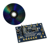
BOARD EVAL LCD BACKLIGHT LED7707
Manufacturer
STMicroelectronics
Specifications of STEVAL-ILL021V1
Design Resources
STEVAL-ILL021V1 Bill of Material STEVAL-ILL021V1 Schematic
Current - Output / Channel
85mA
Outputs And Type
6, Non-Isolated
Voltage - Output
36 V
Features
Dimmable, Extra 5V Output
Voltage - Input
4.5 ~ 36 V
Utilized Ic / Part
LED7707
Description/function
LCD backlight demonstration board
Operating Voltage
4.5 V to 36 V
Product
Display Modules
Core Chip
LED7707
No. Of Outputs
1
Output Voltage
36V
Dimming Control Type
PWM
Mcu Supported Families
LED7707
Lead Free Status / RoHS Status
Lead free by exemption / RoHS compliant by exemption
For Use With/related Products
LED7707
Other names
497-10044
Available stocks
Company
Part Number
Manufacturer
Quantity
Price
Company:

Part Number:
STEVAL-ILL021V1
Manufacturer:
STMicroelectronics
Quantity:
1


LED7707
5.2
5.2.1
Backlight driver section
Current generators
The LED7707 is a LEDs driver with six channels (rows); each row is able to drive multiple
LEDs in series (max. 36 V) and to sink up to 85 mA maximum current, allowing to manage
different kinds of LEDs.
The LEDs current can be set by connecting an external resistor (R
pin and ground. The voltage across the RILIM pin is internally set to 1.23 V and the rows
current is proportional to the RILIM current according to the following equation:
Equation 9
Where K
The graph in
choose the correct value of the resistor to set the desired row current.
Figure 13. Row current vs R
The maximum current mismatch between the rows is ± 2 % @ I
The LED7707 allows parallelism different rows if required by the application. If the maximum
current provided by a single row (85 mA) is not enough for the load, two or more current
generators can be connected together, as shown in
generators stable, the row current should be higher than 40 mA.The connection between
channels in parallel must be done as close as possible to the device in order to minimize
parasitic inductance.
R
= 1850 V.
Figure 13
better shows the relationship between I
RILIM
I
ROWx
=
R
K
RILIM
R
Figure 14
. To keep the parallelism
ROW
rowx
RILIM
and R
Operation description
= 60 mA.
) between the RILIM
RILIM
and helps to
AM00590v1
19/47
Related parts for STEVAL-ILL021V1
Image
Part Number
Description
Manufacturer
Datasheet
Request
R

Part Number:
Description:
BOARD EVAL FOR MEMS SENSORS
Manufacturer:
STMicroelectronics
Datasheet:

Part Number:
Description:
KIT DEV STARTER ST10F276Z5
Manufacturer:
STMicroelectronics
Datasheet:

Part Number:
Description:
BOARD EVAL HDMI $ VIDEO SWITCH
Manufacturer:
STMicroelectronics
Datasheet:

Part Number:
Description:
BOARD DEMO ACCELEROMETER DIL24
Manufacturer:
STMicroelectronics
Datasheet:

Part Number:
Description:
BOARD STLM75/STDS75/ST72F651
Manufacturer:
STMicroelectronics
Datasheet:

Part Number:
Description:
EVAL BOARD 3AXIS MEMS ACCELLRMTR
Manufacturer:
STMicroelectronics
Datasheet:

Part Number:
Description:
BOARD EVAL 8BIT MICRO + TDE1708
Manufacturer:
STMicroelectronics
Datasheet:

Part Number:
Description:
EVAL BOARD A/D TS4657
Manufacturer:
STMicroelectronics
Datasheet:

Part Number:
Description:
BOARD ADAPTER 20DIP LIS3LV02DL
Manufacturer:
STMicroelectronics
Datasheet:

Part Number:
Description:
BOARD DEMO STM8S207R6/LIS331DLH
Manufacturer:
STMicroelectronics
Datasheet:

Part Number:
Description:
STMicroelectronics [RIPPLE-CARRY BINARY COUNTER/DIVIDERS]
Manufacturer:
STMicroelectronics
Datasheet:
Part Number:
Description:
STMicroelectronics [LIQUID-CRYSTAL DISPLAY DRIVERS]
Manufacturer:
STMicroelectronics
Datasheet:
Part Number:
Description:
BOARD EVAL FOR MEMS SENSORS
Manufacturer:
STMicroelectronics
Datasheet: