DM300018 Microchip Technology, DM300018 Datasheet - Page 109
DM300018
Manufacturer Part Number
DM300018
Description
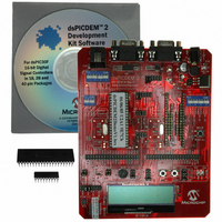
BOARD DEMO DSPICDEM 2
Manufacturer
Microchip Technology
Type
MCUr
Specifications of DM300018
Contents
*
Processor To Be Evaluated
dsPIC30F
Interface Type
RS-232
Silicon Manufacturer
Microchip
Core Architecture
DsPIC
Core Sub-architecture
DsPIC30
Silicon Core Number
DsPIC30F
Silicon Family Name
DsPIC30F2xxx, DsPIC30F3xxx
Lead Free Status / RoHS Status
Not applicable / RoHS Compliant
For Use With/related Products
dsPIC30F
Lead Free Status / Rohs Status
Lead free / RoHS Compliant
Other names
Q2448034
Available stocks
Company
Part Number
Manufacturer
Quantity
Price
Company:

Part Number:
DM300018
Manufacturer:
MICROCHIP
Quantity:
12 000


B.1
B.2
B.3
© 2005 Microchip Technology Inc.
OVERVIEW
LCD HARDWARE SETUP
LCD SOFTWARE SPECIFICATION
A 2x16 ASCII-text LCD is provided on the dsPICDEM2 Development Board. dsPIC30F
devices installed on the dsPICDEM2 development board may use this LCD to display
characters. The interface to the LCD is via a 2-wire Serial Peripheral Interface (SPI™).
dsPIC30F devices may send serial clock and data signals on 2 pins to the
dsPIC30F2011 device that controls the 2x16 LCD.
To enable communication between your dsPIC30F device and the dsPIC30F2011 LCD
controller, simply jumper the appropriate pair of pins on the header H1.For example, in
order to enable communication between the dsPIC30F2010 device and the LCD,
jumpers on the pin-pair labelled “M28” need to be installed on header H1.
The following power-up sequence should be observed by the user's application
firmware when writing characters to the LCD:
1. After any reset operation wait 500 milliseconds to allow the LCD to begin normal
2. Configure SPI1 module on your dsPIC30F device to operate in 8-bit Master
3. To write an ASCII character to the LCD at the location pointed to by the cursor,
4. After the character is displayed on the LCD, the cursor is automatically relocated
5. To reposition the cursor to another column on any of the two rows, write the
6. After 16 characters are written to the first row on the LCD, it is necessary for the
7. The user application must wait for a minimum of 5 milliseconds between writing
8. The user application must wait for a minimum of 250 microseconds after writing
9. The user application must wait for a minimum of 250 microseconds between
operation. The cursor on the LCD will be positioned at the top row on the
left-most column.
mode. The serial clock may be set for any frequency up to 1 MHz.
load the SPIBUF register with the ASCII character byte.
to the next position on the LCD.
address of the desired location to the SPIBUF register. Addresses in the first row
of the LCD range from 0x80 to 0x8F, while addresses on the second row range
from 0xC0 through 0xCF.
user's application to write the address 0xC0 of the second row to the SPIBUF in
order to roll the cursor over to the second row.
two successive characters in the first row of the LCD.
an address byte.
writing two successive characters in the second row of the LCD.
Appendix B. Writing to LCD
Advance Information
DEVELOPMENT BOARD
dsPICDEM™ 2.0
USER’S GUIDE
DS51558A-page 103
Related parts for DM300018
Image
Part Number
Description
Manufacturer
Datasheet
Request
R

Part Number:
Description:
Manufacturer:
Microchip Technology Inc.
Datasheet:
Part Number:
Description:
Manufacturer:
Microchip Technology Inc.
Datasheet:
Part Number:
Description:
Manufacturer:
Microchip Technology Inc.
Datasheet:
Part Number:
Description:
Manufacturer:
Microchip Technology Inc.
Datasheet:
Part Number:
Description:
Manufacturer:
Microchip Technology Inc.
Datasheet:
Part Number:
Description:
Manufacturer:
Microchip Technology Inc.
Datasheet:
Part Number:
Description:
Manufacturer:
Microchip Technology Inc.
Datasheet:
Part Number:
Description:
Manufacturer:
Microchip Technology Inc.
Datasheet: