DM300018 Microchip Technology, DM300018 Datasheet - Page 16
DM300018
Manufacturer Part Number
DM300018
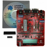
Description
BOARD DEMO DSPICDEM 2
Manufacturer
Microchip Technology
Type
MCUr
Specifications of DM300018
Contents
*
Processor To Be Evaluated
dsPIC30F
Interface Type
RS-232
Silicon Manufacturer
Microchip
Core Architecture
DsPIC
Core Sub-architecture
DsPIC30
Silicon Core Number
DsPIC30F
Silicon Family Name
DsPIC30F2xxx, DsPIC30F3xxx
Lead Free Status / RoHS Status
Not applicable / RoHS Compliant
For Use With/related Products
dsPIC30F
Lead Free Status / Rohs Status
Lead free / RoHS Compliant
Other names
Q2448034
Available stocks
Company
Part Number
Manufacturer
Quantity
Price
Company:

Part Number:
DM300018
Manufacturer:
MICROCHIP
Quantity:
12 000


dsPICDEM 2 Development Board User’s Guide
DS51558A-page 10
FIGURE 1-3:
1.4.2
An RJ11 connector (J1) allows the MPLAB ICD 2 Debugger/Programmer to be used
with the dsPIC30F device you have plugged into the board. Switches S2, S3 and S4
physically connect this interface to the device sockets. Switch S2 connects the MPLAB
ICD 2 interface to the default programming and debugging pins on the dsPIC30F
devices (PGC/EMUC and PGD/EMUD). This switch should be turned on during
programming.
Switches S3 and S4 connect the MPLAB ICD 2 interface to alternative debugging pins
on the dsPIC30F devices (EMUC1/EMUD1 and EMUC2/EMUD2). These switches
should be turned off during device programming and turned on during debugging, if
needed.
1.4.3
A DB9 connector (J2) facilitates external RS-232RS-232 communication. Headers H3,
H4 and H5 connect this interface to the UART peripheral in the dsPIC DSC device.
Header H3 selects UART1. Header H4 selects alternate pins for UART1 in all
dsPIC30F devices supported by this board. Header H5 selects UART2 in dsPIC30F
devices that provide two UARTs (dsPIC30F3011, 3013, 3014, 4011 and 4013).
1.4.4
A second DB9 connector (J3) is used for CAN communication. Header H2 selects the
dsPIC DSC device for the CAN interface. The CAN interface is supported by
dsPIC30F4011, 4012 and 4013 devices.
1.4.5
The dsPICDEM™ 2 power supply
furnishes 9 VDC to the PWR jack (J4). The power supply is split at the regulator to
provide a separate, de-coupled analog supply voltage useful in designs taking
advantage of the dsPIC30F A/D converters. The power supply includes an on-board
+5V regulator for supplying V
Jumpers (JP1 and JP2) let you disconnect the power supply from the board if you want
to supply external DC power via terminals TP1 and TP2.
Sockets for Motor
Control Family
Devices:
dsPIC30F2010
dsPIC30F3010
dsPIC30F3011
dsPIC30F4011
dsPIC30F4012
MPLAB ICD 2 Header
UART Connection
CAN Connection
Power Supply
dsPICDEM™ 2 DEVELOPMENT BOARD LAYOUT
DD
and AV
U2A1
IS
U2B1
powered from an AC/DC wall adapter that
DD
. An LED indicates when the power is on.
U1A1
U1B1
U1C1
© 2005 Microchip Technology Inc.
Sockets for General
Purpose and Sensor
Family Devices:
dsPIC30F2011
dsPIC30F3012
dsPIC30F2012
dsPIC30F3013
dsPIC30F3014
dsPIC30F4013
Related parts for DM300018
Image
Part Number
Description
Manufacturer
Datasheet
Request
R

Part Number:
Description:
Manufacturer:
Microchip Technology Inc.
Datasheet:
Part Number:
Description:
Manufacturer:
Microchip Technology Inc.
Datasheet:
Part Number:
Description:
Manufacturer:
Microchip Technology Inc.
Datasheet:
Part Number:
Description:
Manufacturer:
Microchip Technology Inc.
Datasheet:
Part Number:
Description:
Manufacturer:
Microchip Technology Inc.
Datasheet:
Part Number:
Description:
Manufacturer:
Microchip Technology Inc.
Datasheet:
Part Number:
Description:
Manufacturer:
Microchip Technology Inc.
Datasheet:
Part Number:
Description:
Manufacturer:
Microchip Technology Inc.
Datasheet: