DM300018 Microchip Technology, DM300018 Datasheet - Page 33
DM300018
Manufacturer Part Number
DM300018
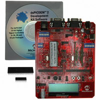
Description
BOARD DEMO DSPICDEM 2
Manufacturer
Microchip Technology
Type
MCUr
Specifications of DM300018
Contents
*
Processor To Be Evaluated
dsPIC30F
Interface Type
RS-232
Silicon Manufacturer
Microchip
Core Architecture
DsPIC
Core Sub-architecture
DsPIC30
Silicon Core Number
DsPIC30F
Silicon Family Name
DsPIC30F2xxx, DsPIC30F3xxx
Lead Free Status / RoHS Status
Not applicable / RoHS Compliant
For Use With/related Products
dsPIC30F
Lead Free Status / Rohs Status
Lead free / RoHS Compliant
Other names
Q2448034
Available stocks
Company
Part Number
Manufacturer
Quantity
Price
Company:

Part Number:
DM300018
Manufacturer:
MICROCHIP
Quantity:
12 000


4.1
4.2
4.3
© 2005 Microchip Technology Inc.
INTRODUCTION
HIGHLIGHTS
BOARD SETUP FOR THE dsPIC30F2011 SAMPLE APPLICATION
This chapter assumes you have chosen the dsPIC30F2011 for your application. The
dsPICDEM 2 Development Board supports a dsPIC30F2011 device in an 18-pin PDIP
package, as shown in Figure 4-1. This device provides eight 12-bit A/D (100 ksps)
channels, a UART, an SPI module, an I
tion program provides a software baseline for building your own embedded solution.
FIGURE 4-1:
This chapter discusses:
• Board Setup for the dsPIC30F2011 Sample Application
• Device Programming
• Observing the Sample Application
• In-Circuit debugging
• Summary
The dsPICDEM 2 Development Board supports dsPIC30F devices that have multiple
peripheral devices multiplexed on some pins. Therefore, the jumper set up of various
headers depends on which of the dsPIC30F peripherals are used by the application.
This section demonstrates how the board is set up for the dsPIC30F2011 device to
support the dsPIC30F2011 example software in the dsPICDEM 2 Development Kit CD.
Follow these steps to configure the hardware on the dsPICDEM 2 Development Board
for the sample application.
1. Disconnect the power source.
2. Remove any dsPIC30Fxxxx device currently plugged into the dsPICDEM 2
3. Plug the dsPIC30F2011 into socket U1C1.
Chapter 4. Using the dsPIC30F2011
U1A1
Development Board.
EMUC1/SOSCO/T1CK/U1ARX/CN0/RC14
EMUD1/SOSCI/T2CK/U1ATX/CN1/RC13
EMUD3\AN0/V
EMUD3\AN1/V
AN2/SS1/LVDIN/CN4/RB2
18-PIN PDIP dsPIC30F2011
OSC2/CLKO/RC15
REF
AN3/CN5/RB3
REF
OSC1/CLKI
+/CN2/RB0
-/CN3/RB1
MCLR
1
2
3
4
5
6
7
8
9
DEVELOPMENT BOARD
2
C module and 12 I/O pins. A sample applica-
18
17
16
15
14
13
12
10
11
V
AV
AV
AN6/SCK1/INT0/OCFA/RB6
EMUD2/AN7/OC2/IC2/INT2/RB7
V
PGC/EMUC/AN5/U1RX/SDI1/SDA/CN7/RB5
PGD/EMUD/AN4/U1TX/SDO1/SCL/CN6/RB4
EMUC2/OC1/IC1/INT1/RD0
DD
SS
DD
SS
USER’S GUIDE
dsPICDEM™ 2
DS51558A-page 27
Related parts for DM300018
Image
Part Number
Description
Manufacturer
Datasheet
Request
R

Part Number:
Description:
Manufacturer:
Microchip Technology Inc.
Datasheet:
Part Number:
Description:
Manufacturer:
Microchip Technology Inc.
Datasheet:
Part Number:
Description:
Manufacturer:
Microchip Technology Inc.
Datasheet:
Part Number:
Description:
Manufacturer:
Microchip Technology Inc.
Datasheet:
Part Number:
Description:
Manufacturer:
Microchip Technology Inc.
Datasheet:
Part Number:
Description:
Manufacturer:
Microchip Technology Inc.
Datasheet:
Part Number:
Description:
Manufacturer:
Microchip Technology Inc.
Datasheet:
Part Number:
Description:
Manufacturer:
Microchip Technology Inc.
Datasheet: