DM300018 Microchip Technology, DM300018 Datasheet - Page 98
DM300018
Manufacturer Part Number
DM300018
Description
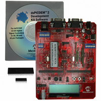
BOARD DEMO DSPICDEM 2
Manufacturer
Microchip Technology
Type
MCUr
Specifications of DM300018
Contents
*
Processor To Be Evaluated
dsPIC30F
Interface Type
RS-232
Silicon Manufacturer
Microchip
Core Architecture
DsPIC
Core Sub-architecture
DsPIC30
Silicon Core Number
DsPIC30F
Silicon Family Name
DsPIC30F2xxx, DsPIC30F3xxx
Lead Free Status / RoHS Status
Not applicable / RoHS Compliant
For Use With/related Products
dsPIC30F
Lead Free Status / Rohs Status
Lead free / RoHS Compliant
Other names
Q2448034
Available stocks
Company
Part Number
Manufacturer
Quantity
Price
Company:

Part Number:
DM300018
Manufacturer:
MICROCHIP
Quantity:
12 000


dsPICDEM 2 Development Board User’s Guide
DS51558A-page 92
14.1.8
Switches S5 and S6 can be connected to the external interrupt pins, INT0 and INT1,
respectively on all supported dsPIC30F devices. Switches S5 and S6 are connected to
the dsPIC DSC device through headers H6 and H7, respectively. The signal lines are
normally pulled up to +5V DC through 4.7 kOhm resistors. Pressing the switch will short
the line to ground.
Table 14-4 lists the connections set up by the jumper positions on headers H6 and H7.
TABLE 14-5:
The schematic of the pushbutton switches and selection headers that comprise the
simulated external interrupt circuits is shown in Figure A-7: “dsPICDEM™ 2
Development Board Schematic (Sheet 6 of 7)”.
14.1.9
Two LEDs D3 and D4 are provided on the dsPICDEM 2 Development Board. These
may be useful in monitoring the status of your application. The LEDs, D3 and D4, are
connected to port pins, RB0 and RB1, on the dsPIC30F devices, respectively. These
LEDs will illuminate if a high signal is fed to them, but will turn off on a low signal.
Header H12 is used to connect the LEDs, D3 and D4, into the circuit. If the jumper is
installed to connect the GP pins, the LED is connected to the General Purpose and
Sensor family device sockets (U1A1, U1B1 and U1C1). If the jumper on H12 is installed
to connect the M ALL pins, the LED is connected to the motor control device sockets
(U2A1 and U2B1).
The schematic of the LED indicator circuits is shown in Figure A-7: “dsPICDEM™ 2
Development Board Schematic (Sheet 6 of 7)”.
H6
H7
Note 1:
Header
2:
(1)
Header H6 selects switch S5 (INT0). Header H7 selects switch S6 (INT1).
Indicates the path established when jumper is installed in that position.
External Interrupt Switches
LED Indicators
GP 40
GP 28
GP 18
M ALL
GP 40/28
GP 18
M ALL
Pin Position
EXTERNAL INTERRUPT HEADER SETTINGS
Connects switch S5 to Port pin RA11of the 40-pin dsPIC30F
device in general purpose socket U1A1 to signify external
interrupt INT0.
Connects switch S5 to Port pin RF6 of the 28-pin dsPIC30F
device in general purpose socket U1B1 to signify external
interrupt INT0.
Connects switch S5 to Port pin RB6 of the 18-pin dsPIC30F
device in general purpose socket U1C1 to signify external
interrupt INT0.
Connects switch S5 to Port pin RE8 of the dsPIC30F device in
either motor control socket to signify external interrupt INT0.
Connects switch S6 to Port pin RD8 of the 28 or 40-pin
dsPIC30F device in general purpose socket U1B1 or U1A1 to
signify external interrupt INT1.
Connects switch S6 to Port pin RD0 of the 18-pin dsPIC30F
device in general purpose socket U1C1 to signify external
interrupt INT1.
Connects switch S6 to Port pin RD0 of the dsPIC30F device in
either motor control socket to signify external interrupt INT0.
Function
© 2005 Microchip Technology Inc.
(2)
Related parts for DM300018
Image
Part Number
Description
Manufacturer
Datasheet
Request
R

Part Number:
Description:
Manufacturer:
Microchip Technology Inc.
Datasheet:
Part Number:
Description:
Manufacturer:
Microchip Technology Inc.
Datasheet:
Part Number:
Description:
Manufacturer:
Microchip Technology Inc.
Datasheet:
Part Number:
Description:
Manufacturer:
Microchip Technology Inc.
Datasheet:
Part Number:
Description:
Manufacturer:
Microchip Technology Inc.
Datasheet:
Part Number:
Description:
Manufacturer:
Microchip Technology Inc.
Datasheet:
Part Number:
Description:
Manufacturer:
Microchip Technology Inc.
Datasheet:
Part Number:
Description:
Manufacturer:
Microchip Technology Inc.
Datasheet: