DM300018 Microchip Technology, DM300018 Datasheet - Page 20
DM300018
Manufacturer Part Number
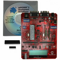
DM300018
Description
BOARD DEMO DSPICDEM 2
Manufacturer
Microchip Technology
Type
MCUr
Specifications of DM300018
Contents
*
Processor To Be Evaluated
dsPIC30F
Interface Type
RS-232
Silicon Manufacturer
Microchip
Core Architecture
DsPIC
Core Sub-architecture
DsPIC30
Silicon Core Number
DsPIC30F
Silicon Family Name
DsPIC30F2xxx, DsPIC30F3xxx
Lead Free Status / RoHS Status
Not applicable / RoHS Compliant
For Use With/related Products
dsPIC30F
Lead Free Status / Rohs Status
Lead free / RoHS Compliant
Other names
Q2448034
Available stocks
Company
Part Number
Manufacturer
Quantity
Price
Company:

Part Number:
DM300018
Manufacturer:
MICROCHIP
Quantity:
12 000


dsPICDEM 2 Development Board User’s Guide
2.4
DS51558A-page 14
OUT-OF-THE-BOX DEMO
Out-of-the-box, you can power up the dsPICDEM™ 2 Development Board and run the
sample application on the dsPIC30F4011 device. The objective of this process is to
acquaint you with the board and demonstrate how the dsPIC30F device interacts with
the hardware components used for the demo (see Section 2.4 “Out-of-the-Box
Demo”).
Eventually, as you develop your own application, you will need to program and debug
the dsPIC30F device. The second phase of the getting-started process is programming
the device for stand-alone operation. For this process, you attach the MPLAB ICD 2
In-Circuit Debugger to the dsPICDEM 2 board, designate it as a programmer in MPLAB
IDE, build your program in MPLAB IDE and then program the device with MPLAB ICD
2. The procedures for this process are outline in Section 2.5 “Device Programming
Process”, using the dsPIC30F4011 device as an example.
To examine program operation on a step-by-step basis, you need to set up MPLAB ICD
2 as a debugger. For this process you attach the MPLAB ICD 2 In-Circuit Debugger to
the dsPICDEM 2 board, designate it as a debugger in MPLAB IDE, build your program
in MPLAB IDE and then program the device for debug mode with MPLAB ICD 2. The
procedures for this process are outline in Section 2.6 “In-Circuit Debugging
Process”, using the dsPIC30F4011 device as an example.
As the first phase of your getting-started process, you only need to connect your PC to
the dsPICDEM™ 2 Development Board, apply power to the board and observe the
sample application on the board and on HyperTerminal
2.4.1
Out-of-the-box, the dsPICDEM™ 2 Development Board is configured to operate with
the dsPIC304011 device. When you use a different type of supported device you need
to reconfigure the board for that device. In general, you follow this process to reconfig-
ure the dsPICDEM™ 2 Development Board. For the out-of-the-box configuration, you
simply can verify these settings:
1. Select a supported dsPIC30F device and plug it into the appropriate socket (not
2. Note the hardware configuration for the dsPIC30F4011device:
Note:
necessary out of the box).
This functionality:
Program/Debug device
Alternate Debugging
Temperature (A/D)
Potentiometer (A/D)
CAN
UART1
Alternate UART1
UART2
LCD (SPI)
SPI™ Controller ProgrammingH11 open
Switch S5 (INT0)
Switch S6 (INT1)
External connections
LEDs D3 and D4 (I/O)
Power Supply
dsPICDEM 2 Configuration
Chapters 3-13 provide specific set-up instructions for each type of
dsPIC30F device supported by the dsPICDEM™ 2 Development Board.
Jumpers JP1 and JP2
Is set up by this hardware component:
Switch S2 switched OFF
Switch S3 or S4 – all switches OFF
H10 set to M ALL
H13 set to M ALL
H2 open
H3 open
H4 set to M ALL
H5 open
H1 set to M 40
H6 set to M ALL
H7 set to M ALL
H8 or H9 open
H12 set to M
®
.
© 2005 Microchip Technology Inc.
Related parts for DM300018
Image
Part Number
Description
Manufacturer
Datasheet
Request
R

Part Number:
Description:
Manufacturer:
Microchip Technology Inc.
Datasheet:
Part Number:
Description:
Manufacturer:
Microchip Technology Inc.
Datasheet:
Part Number:
Description:
Manufacturer:
Microchip Technology Inc.
Datasheet:
Part Number:
Description:
Manufacturer:
Microchip Technology Inc.
Datasheet:
Part Number:
Description:
Manufacturer:
Microchip Technology Inc.
Datasheet:
Part Number:
Description:
Manufacturer:
Microchip Technology Inc.
Datasheet:
Part Number:
Description:
Manufacturer:
Microchip Technology Inc.
Datasheet:
Part Number:
Description:
Manufacturer:
Microchip Technology Inc.
Datasheet: