DK-MAXII-1270N Altera, DK-MAXII-1270N Datasheet - Page 3
DK-MAXII-1270N
Manufacturer Part Number
DK-MAXII-1270N
Description
KIT DEV MAXII W/EPM 1270N
Manufacturer
Altera
Series
MAX® IIr
Type
CPLDr
Specifications of DK-MAXII-1270N
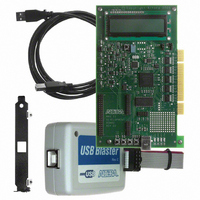
Contents
Dev Board, Quartus®II Web Edition, Nios®II Web Edition, Cables, Accessories, Reference Designs and Demos
Silicon Manufacturer
Altera
Core Architecture
CPLD
Core Sub-architecture
MAX
Silicon Core Number
EPM
Silicon Family Name
MAX II
Rohs Compliant
Yes
For Use With/related Products
MAX®II CPLDs
Lead Free Status / RoHS Status
Lead free / RoHS Compliant
Other names
544-2380
Available stocks
Company
Part Number
Manufacturer
Quantity
Price


Altera Corporation
Circuits
Active I/O sensor
Current sensor
Schmitt trigger
Components
66-MHz oscillator
Temperature sensor
User push-button
switches
User LEDs
Status LEDs
LCD
SRAM
PCI quickswitches
Potentiometer
Interfaces
USB
PCI
Altera Expansion
Prototype Header
Prototyping area
Component/Interface
Table 1. MAX II Development Board Components & Interfaces
Circuit
Circuit
Circuit
Clock
I/O
Input
Output
Status
I/O
Memory
I/O
I/O
I/O
I/O
I/O
I/O
Type
Table 1
supports.
Environmental Requirements
The MAX II development board must be stored between –40° C and
100° C. The recommended operating temperature is between 0° C and
55° C.
1
describes the components on the board and the interfaces it
Active I/O test points
U2, U19, U23
R13, C8
U3
U1
S1, S2, S3, S4
LED1, LED2, LED3,
LED4
LED5, LED6, LED7,
LED8, LED9, LED10
LCD1
U5
U7, U8, U9, U10, U11 Convert 5.0-V PCI signals into 3.3-V signals
POT1
U13
B1, B62, A1, A62
J3, J4, J5
PA1
The MAX II development board can be damaged without
proper anti-static handling.
Board Designation
Circuit for investigating MAX II power
optimization
Power measuring circuit
RC circuit for investigating the internal Schmitt
trigger in MAX II devices
Main clock for MAX II board
Allows designer to measure board temperature
User-definable push-button switches
User-definable LEDs
Indicate which components are receiving power
On-board LCD
1 Mbit of SRAM
Adjusts the load on the V
Universal serial bus media access controller
PCI edge connector
Daughter card header
Allows designer to add custom components to
the MAX II development board
Description
C C I N T
General Description
plane
Preliminary
3
Related parts for DK-MAXII-1270N
Image
Part Number
Description
Manufacturer
Datasheet
Request
R

Part Number:
Description:
KIT DEV MAX V 5M570Z
Manufacturer:
Altera
Datasheet:

Part Number:
Description:
CYCLONE II STARTER KIT EP2C20N
Manufacturer:
Altera
Datasheet:


Part Number:
Description:
CPLD, EP610 Family, ECMOS Process, 300 Gates, 16 Macro Cells, 16 Reg., 16 User I/Os, 5V Supply, 35 Speed Grade, 24DIP
Manufacturer:
Altera Corporation
Datasheet:
Part Number:
Description:
CPLD, EP610 Family, ECMOS Process, 300 Gates, 16 Macro Cells, 16 Reg., 16 User I/Os, 5V Supply, 15 Speed Grade, 24DIP
Manufacturer:
Altera Corporation
Datasheet:
Part Number:
Description:
Manufacturer:
Altera Corporation
Datasheet:
Part Number:
Description:
CPLD, EP610 Family, ECMOS Process, 300 Gates, 16 Macro Cells, 16 Reg., 16 User I/Os, 5V Supply, 30 Speed Grade, 24DIP
Manufacturer:
Altera Corporation
Datasheet:
Part Number:
Description:
High-performance, low-power erasable programmable logic devices with 8 macrocells, 10ns
Manufacturer:
Altera Corporation
Datasheet:
Part Number:
Description:
High-performance, low-power erasable programmable logic devices with 8 macrocells, 7ns
Manufacturer:
Altera Corporation
Datasheet:
Part Number:
Description:
Classic EPLD
Manufacturer:
Altera Corporation
Datasheet:
Part Number:
Description:
High-performance, low-power erasable programmable logic devices with 8 macrocells, 10ns
Manufacturer:
Altera Corporation
Datasheet:
Part Number:
Description:
Manufacturer:
Altera Corporation
Datasheet:
Part Number:
Description:
Manufacturer:
Altera Corporation
Datasheet:
Part Number:
Description:
Manufacturer:
Altera Corporation
Datasheet: