DK-MAXII-1270N Altera, DK-MAXII-1270N Datasheet - Page 4
DK-MAXII-1270N
Manufacturer Part Number
DK-MAXII-1270N
Description
KIT DEV MAXII W/EPM 1270N
Manufacturer
Altera
Series
MAX® IIr
Type
CPLDr
Specifications of DK-MAXII-1270N
Contents
Dev Board, Quartus®II Web Edition, Nios®II Web Edition, Cables, Accessories, Reference Designs and Demos
Silicon Manufacturer
Altera
Core Architecture
CPLD
Core Sub-architecture
MAX
Silicon Core Number
EPM
Silicon Family Name
MAX II
Rohs Compliant
Yes
For Use With/related Products
MAX®II CPLDs
Lead Free Status / RoHS Status
Lead free / RoHS Compliant
Other names
544-2380
Available stocks
Company
Part Number
Manufacturer
Quantity
Price


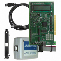
MAX II Development Board
Using the Board
4
Preliminary
This section provides information on using the MAX II development
board.
Apply Power
Power can be applied to the board from the USB or PCI bus. Jumper J8
controls which source supplies power. If the shunt is on pins 1 and 2, the
board will be powered via the USB bus. If the shunt is on pins 2 and 3, the
board will be powered via the PCI bus. Pin 1 of J8 is the pin closest to the
LCD. When the board is powered up, the LED power indicators (LEDs 5,
6, 7, 8, 9, and 10) will illuminate.
Program the MAX II Device
The MAX II device on the MAX II development board can be
programmed using the Quartus
designer must supply power as indicated above and then connect the
ByteBlaster™ cable to the 10-pin JTAG header on the board (J2). More
detail on programming MAX II devices is available in the MAX II
Development Kit Getting Started User Guide and Quartus II Help.
w
The Quartus II software default setting in the Unused Pins tab
leaves unused pins as outputs, driving ground. When compiling
designs that target Altera development boards, change this
setting so that unused pins act as inputs and are tri-stated. The
reason for this change is that components on the board may be
damaged by having GND signals driven onto pins that drive
V
and they are tri-stated, then they will not damage the board. To
change this option in the Quartus II software, select Settings
(Assignments menu). In the menu on the right, click Device,
then click Device and Pin Options. In the Device & Pin
Options dialog box, click the Unused Pins tab. Ensure this
option is set to As inputs, tri-stated. See
CC
. However, if you set these unused pins to behave as inputs
®
II software. To program the board, the
Figure
Altera Corporation
2.
Related parts for DK-MAXII-1270N
Image
Part Number
Description
Manufacturer
Datasheet
Request
R

Part Number:
Description:
KIT DEV MAX V 5M570Z
Manufacturer:
Altera
Datasheet:

Part Number:
Description:
CYCLONE II STARTER KIT EP2C20N
Manufacturer:
Altera
Datasheet:


Part Number:
Description:
CPLD, EP610 Family, ECMOS Process, 300 Gates, 16 Macro Cells, 16 Reg., 16 User I/Os, 5V Supply, 35 Speed Grade, 24DIP
Manufacturer:
Altera Corporation
Datasheet:
Part Number:
Description:
CPLD, EP610 Family, ECMOS Process, 300 Gates, 16 Macro Cells, 16 Reg., 16 User I/Os, 5V Supply, 15 Speed Grade, 24DIP
Manufacturer:
Altera Corporation
Datasheet:
Part Number:
Description:
Manufacturer:
Altera Corporation
Datasheet:
Part Number:
Description:
CPLD, EP610 Family, ECMOS Process, 300 Gates, 16 Macro Cells, 16 Reg., 16 User I/Os, 5V Supply, 30 Speed Grade, 24DIP
Manufacturer:
Altera Corporation
Datasheet:
Part Number:
Description:
High-performance, low-power erasable programmable logic devices with 8 macrocells, 10ns
Manufacturer:
Altera Corporation
Datasheet:
Part Number:
Description:
High-performance, low-power erasable programmable logic devices with 8 macrocells, 7ns
Manufacturer:
Altera Corporation
Datasheet:
Part Number:
Description:
Classic EPLD
Manufacturer:
Altera Corporation
Datasheet:
Part Number:
Description:
High-performance, low-power erasable programmable logic devices with 8 macrocells, 10ns
Manufacturer:
Altera Corporation
Datasheet:
Part Number:
Description:
Manufacturer:
Altera Corporation
Datasheet:
Part Number:
Description:
Manufacturer:
Altera Corporation
Datasheet:
Part Number:
Description:
Manufacturer:
Altera Corporation
Datasheet: