DK-MAXII-1270N Altera, DK-MAXII-1270N Datasheet - Page 6
DK-MAXII-1270N
Manufacturer Part Number
DK-MAXII-1270N
Description
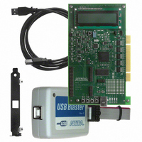
KIT DEV MAXII W/EPM 1270N
Manufacturer
Altera
Series
MAX® IIr
Type
CPLDr
Specifications of DK-MAXII-1270N
Contents
Dev Board, Quartus®II Web Edition, Nios®II Web Edition, Cables, Accessories, Reference Designs and Demos
Silicon Manufacturer
Altera
Core Architecture
CPLD
Core Sub-architecture
MAX
Silicon Core Number
EPM
Silicon Family Name
MAX II
Rohs Compliant
Yes
For Use With/related Products
MAX®II CPLDs
Lead Free Status / RoHS Status
Lead free / RoHS Compliant
Other names
544-2380
Available stocks
Company
Part Number
Manufacturer
Quantity
Price


MAX II Development Board
Figure 3. MAX II Development Board Block Diagram
6
Preliminary
16 × 2 Character
Pushbuttons
LCD Display
User
Interface
USB
4 Outputs
4 Inputs
Display
FIFO
Bus
Bus
Power
You can power the MAX II development board from either the PCI bus or
the USB bus. If you are not using the board in the PCI slot of a PC, then
you must power the board from the USB bus. Jumper J8 is used to select
which bus powers the board. If the shunt is on pins 1 and 2, the board will
be powered via the USB bus. If the shunt is on pins 2 and 3, the board will
be powered via the PCI bus. Pin 1 of J8 is the pin closest to the LCD.
The PCI bus or the USB bus routes the power to six different regulators,
which power individual board components. The MAX II device is
powered from either a 2.5-V or a 3.3-V power supply. You select which
supply voltage to use (for V
load) of V
Power-Up Sequence
When you apply power to the MAX II development board, the 5.0-V
power supply powers up first, because it is the source for the 3.3-V/2.5-V
power supply. The 3.3-V/2.5-V V
increase or decrease the rate at which the V
LEDs
EPM1270F256C5
CCINT
MAX II
Device
PCI Bus
can be adjusted by the potentiometer (POT1).
SPI
Bus
SPI
4 Channels
8 Bits
ADC
CCINT
Power Distribution Controls
Address
Data
Bus
Bus
CCINT
Temperature
) by using jumper J9. The slew rate (or
Reg
Reg
Sensor
Current
Sensor
supply powers up second. You can
128K × 8
SRAM
Amplifier
CCINT
supply comes up by
Supply
Power
Indicator
Power
Altera Corporation
with Ramp
Interrupt
V
Control
CCINT
Related parts for DK-MAXII-1270N
Image
Part Number
Description
Manufacturer
Datasheet
Request
R

Part Number:
Description:
KIT DEV MAX V 5M570Z
Manufacturer:
Altera
Datasheet:

Part Number:
Description:
CYCLONE II STARTER KIT EP2C20N
Manufacturer:
Altera
Datasheet:


Part Number:
Description:
CPLD, EP610 Family, ECMOS Process, 300 Gates, 16 Macro Cells, 16 Reg., 16 User I/Os, 5V Supply, 35 Speed Grade, 24DIP
Manufacturer:
Altera Corporation
Datasheet:
Part Number:
Description:
CPLD, EP610 Family, ECMOS Process, 300 Gates, 16 Macro Cells, 16 Reg., 16 User I/Os, 5V Supply, 15 Speed Grade, 24DIP
Manufacturer:
Altera Corporation
Datasheet:
Part Number:
Description:
Manufacturer:
Altera Corporation
Datasheet:
Part Number:
Description:
CPLD, EP610 Family, ECMOS Process, 300 Gates, 16 Macro Cells, 16 Reg., 16 User I/Os, 5V Supply, 30 Speed Grade, 24DIP
Manufacturer:
Altera Corporation
Datasheet:
Part Number:
Description:
High-performance, low-power erasable programmable logic devices with 8 macrocells, 10ns
Manufacturer:
Altera Corporation
Datasheet:
Part Number:
Description:
High-performance, low-power erasable programmable logic devices with 8 macrocells, 7ns
Manufacturer:
Altera Corporation
Datasheet:
Part Number:
Description:
Classic EPLD
Manufacturer:
Altera Corporation
Datasheet:
Part Number:
Description:
High-performance, low-power erasable programmable logic devices with 8 macrocells, 10ns
Manufacturer:
Altera Corporation
Datasheet:
Part Number:
Description:
Manufacturer:
Altera Corporation
Datasheet:
Part Number:
Description:
Manufacturer:
Altera Corporation
Datasheet:
Part Number:
Description:
Manufacturer:
Altera Corporation
Datasheet: