P0528 Terasic Technologies Inc, P0528 Datasheet - Page 27
P0528
Manufacturer Part Number
P0528
Description
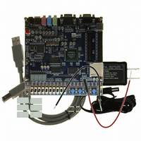
BOARD DEV DE1 ALTERA
Manufacturer
Terasic Technologies Inc
Type
FPGAr
Datasheet
1.P0528.pdf
(56 pages)
Specifications of P0528
Contents
DE1 Board, Power Supply, USB Cable, Plastic cover and software
For Use With/related Products
Cyclone II 2C20
For Use With
P0033 - BOARD ADAPTER HSMC TO GPIOP0006 - BOARD ADAPTER THDB-SUMP0001 - MODULE DIGITAL CAMERA 5MP (D5M)P0307 - KIT DEV 4.3" LCD TOUCH PANEL
Lead Free Status / RoHS Status
Lead free / RoHS Compliant
Other names
DE1


Figure 4.1 illustrates the JTAG configuration setup. To download a configuration bit stream into the
Cyclone II FPGA, perform the following steps:
Configuring the EPCS4 in AS Mode
Figure 4.2 illustrates the AS configuration set up. To download a configuration bit stream into the
EPCS4 serial EEPROM device, perform the following steps:
• Ensure that power is applied to the DE1 board
• Connect the supplied USB cable to the USB Blaster port on the DE1 board (see Figure 2.1)
• Configure the JTAG programming circuit by setting the RUN/PROG switch (on the left side
• The FPGA can now be programmed by using the Quartus II Programmer module to select a
• Ensure that power is applied to the DE1 board
• Connect the supplied USB cable to the USB Blaster port on the DE1 board (see Figure 2.1)
• Configure the JTAG programming circuit by setting the RUN/PROG switch (on the left side
• The EPCS4 chip can now be programmed by using the Quartus II Programmer module to
• Once the programming operation is finished, set the RUN/PROG switch back to the RUN
of the board) to the RUN position.
configuration bit stream file with the .sof filename extension
Quartus II
Programmer
of the board) to the PROG position.
select a configuration bit stream file with the .pof filename extension
position and then reset the board by turning the power switch off and back on; this action
causes the new configuration data in the EPCS4 device to be loaded into the FPGA chip.
USB
USB Blaster Circuit
Figure 4.1. The JTAG configuration scheme.
MAX
3128
PROG/RUN
"RUN"
EPCS4
Serial
Configuration
Device
25
JTAG Config Signals
JTAG UART
Auto
Power-on Config
JTAG Config Port
FPGA
DE1 User Manual
Related parts for P0528
Image
Part Number
Description
Manufacturer
Datasheet
Request
R

Part Number:
Description:
MODULE DIGITAL CAMERA 5MP (D5M)
Manufacturer:
Terasic Technologies Inc
Datasheet:

Part Number:
Description:
DE2-70 CALL FOR ACADEMIC PRICING
Manufacturer:
Terasic Technologies Inc
Datasheet:

Part Number:
Description:
USB BLASTER CABLE
Manufacturer:
Terasic Technologies Inc
Datasheet:

Part Number:
Description:
BOARD ADAPTER HSMC TO GPIO
Manufacturer:
Terasic Technologies Inc
Datasheet:

Part Number:
Description:
BOARD ADAPTER THDB-SUM
Manufacturer:
Terasic Technologies Inc
Datasheet:

Part Number:
Description:
KIT DEV 4.3" LCD TOUCH PANEL
Manufacturer:
Terasic Technologies Inc
Datasheet:

Part Number:
Description:
DAUGHTER BOARD AD/DA GPIO ADA
Manufacturer:
Terasic Technologies Inc

Part Number:
Description:
DAUGHTER BOARD AD/DA HSMC ADA
Manufacturer:
Terasic Technologies Inc

Part Number:
Description:
KIT MAX II MICRO
Manufacturer:
Terasic Technologies Inc
Datasheet:

Part Number:
Description:
BOARD DEV/EDUCATION ALTERA DE0
Manufacturer:
Terasic Technologies Inc
Datasheet:

Part Number:
Description:
DE2 CALL FOR ACADEMIC PRICING
Manufacturer:
Terasic Technologies Inc

Part Number:
Description:
MODULE DIGITAL CAMERA 1.3MP
Manufacturer:
Terasic Technologies Inc
Datasheet:

Part Number:
Description:
SENSOR CMOS 1.3MEGA (FOR P0349)
Manufacturer:
Terasic Technologies Inc
Datasheet:
Part Number:
Description:
MODULE DIGITAL CAMERA 5MP (D5M)
Manufacturer:
Terasic Technologies Inc
Datasheet: