XE8000EV110 Semtech, XE8000EV110 Datasheet - Page 154
XE8000EV110
Manufacturer Part Number
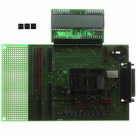
XE8000EV110
Description
EVAL BOARD FOR XE8802AMI035LF
Manufacturer
Semtech
Type
MCUr
Specifications of XE8000EV110
Contents
Fully Assembled Evaluation Board
For Use With/related Products
XE88LC02MI035
Lead Free Status / RoHS Status
Contains lead / RoHS non-compliant


The LCD driver is set to 1:2 multiplexing (LcdMux=01 in RegLcdOn) and the waveform generator is enabled
(LcdSleep=0 in RegLcdOn). All pads are set into the LCD driver mode by setting all bits of register RegLcdSe to
1. To select a frame rate of about 50Hz, set the bits LcdFreq=01 and LcdDivFreq=100 in RegLcdClkFrame. Note
that the precision of the frame frequency depends on the selected clock source (see clock block documentation).
The 64 segments are on or off depending on the bits set in the registers RegLcdDataN. Only the bits 0,1 and 4,5 of
these registers are used in 1:2 multiplexing. Figure 19-5 shows the generated waveforms for four segments.
Segments connected to pad_lcd_io[0] are on (LcdData0[1:0]=11 in RegLcdData0) and segments connected to
pad_lcd_io[1] are off (LcdData0[5:4]=00 in RegLcdData0). The figure shows on the left side the waveforms on the
circuit pins, in the middle the segment status and on the right the voltage on the segment (difference between the
segment pin pad_lcd_io and common signal pad_lcd_com0 or pad_lcd_com1).
© Semtech 2006
pad_lcd_com0
pad_lcd_com1
pad_lcd_io[0]
pad_lcd_io[1]
V3
V2
V0
V3
V2
V0
V3
V2
V0
V3
V2
V0
Figure 19-5. 1:2 MUX mode waveforms
XE8802 Sensing Machine Data Acquisition MCU
19-10
with ZoomingADC™ and LCD driver
-V2
-V3
-V2
-V3
V3
V2
V0
V3
V2
V0
pad_lcd_com0 - pad_lcd_io[0] (on)
pad_lcd_com1 - pad_lcd_io[1] (off)
www.semtech.com
Related parts for XE8000EV110
Image
Part Number
Description
Manufacturer
Datasheet
Request
R

Part Number:
Description:
EVALUATION BOARD
Manufacturer:
Semtech
Datasheet:
Part Number:
Description:
EVALUATION BOARD
Manufacturer:
Semtech
Datasheet:
Part Number:
Description:
VOLTAGE SUPPRESSOR, TRANSIENT SEMTECH
Manufacturer:
Semtech
Datasheet:

Part Number:
Description:
HIGH VOLTAGE CAPACITORS MONOLITHIC CERAMIC TYPE
Manufacturer:
Semtech Corporation
Datasheet:
Part Number:
Description:
EZ1084CM5.0 AMP POSITIVE VOLTAGE REGULATOR
Manufacturer:
Semtech Corporation
Datasheet:
Part Number:
Description:
3.0 AMP LOW DROPOUT POSITIVE VOLTAGE REGULATORS
Manufacturer:
Semtech Corporation
Datasheet:
Part Number:
Description:
Manufacturer:
Semtech Corporation
Datasheet:
Part Number:
Description:
RailClamp Low Capacitance TVS Diode Array
Manufacturer:
Semtech Corporation
Datasheet:
Part Number:
Description:
Manufacturer:
Semtech Corporation
Datasheet:
Part Number:
Description:
Manufacturer:
Semtech Corporation
Datasheet:
Part Number:
Description:
Manufacturer:
Semtech Corporation
Datasheet:
Part Number:
Description:
Manufacturer:
Semtech Corporation
Datasheet: