XE8000EV110 Semtech, XE8000EV110 Datasheet - Page 171
XE8000EV110
Manufacturer Part Number
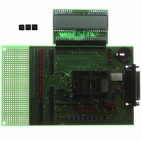
XE8000EV110
Description
EVAL BOARD FOR XE8802AMI035LF
Manufacturer
Semtech
Type
MCUr
Specifications of XE8000EV110
Contents
Fully Assembled Evaluation Board
For Use With/related Products
XE88LC02MI035
Lead Free Status / RoHS Status
Contains lead / RoHS non-compliant


As can be seen from Table 19-28, the voltage V3 on the pins pad_lcd_io[31:12] can not be dissociated from the
voltage V3 on the pins pad_lcd_com0, pad_lcd_com1 and the internal voltage multiplier/divider. It means that, if V3
is not a low impedance external voltage as in the previous section, they can be used for the LCD driver only and
not for digital I/O.
Figure 19-21 and Table 19-29 show an example. In this case, the pins pad_lcd_io[29:12] are used to drive a
display with 1:4 multiplexing (LcdSe15=LcdSe19=LcdSe23=Lcd27=Lcd31=1 in RegLcdSe and LcdMux=11 in
RegLcdOn). In 1:4 multiplexing, the lines pad_lcd_io[31:30] are used for COM2 and COM3. The voltage V3 for the
display is generated by the internal voltage multiplier/divider using the internal reference (VgenOff=0,
VgenRefEn=1, VgenMode=0 in RegVgenCfg0). The segment status is set by using the RegLcdDataN registers
with 6≤N≤15. Writing in the registers with 0≤N≤5 will have no effect. The pins pad_lcd_io[11:0] are used as digital
I/O (LcdSe3=LcdSe7=LcdSe11=0 in RegLcdSe). The control of the digital I/O is done using the registers
RegPLcdInN, RegPLcdOutN, RegPLcdDirN and RegPLcdPullupN with 0≤N≤1. Writing in the registers with
2≤N≤3 will have no effect. The pins pad_lcd_io[11:4] and pad_lcd_io[3:0] can further be split into two different
voltage domains. The voltage domains VDD1, VDD2, V3 and VBAT are independent. The only limitation is that
VDD1>VREG and VDD2>VREG. In the example V3=3.6V, VBAT could be at 2.7V, VDD1 at 2.4V and VDD2 at 5V.
19.8 Specifications
19.8.1
(1) rise or fall time from 10% to 90% of the output signal
(2) Cload=5000pF
(3) V1=V2/2=V3/3=1.1V (1/3 bias) or V1=V2=V3/2=1.1V (1/2 bias)
19.8.2
(1) rise or fall time from 10% to 90% of the output signal
(2) with Cload=5nF, pad_vgen_v3=pad_lcd_vr1=pad_lcd_vr2=2.4V
(3) pad_vgen_v3=pad_lcd_vr1=pad_lcd_vr2=4.5V, voltage on pad_lcd_io=0.4V for sink current and 4.1V for
source current.
© Semtech 2006
Specification
V1
V2, V3
t
Specification
pad_lcd_vr1
pad_lcd_vr2
pad_vgen_v3
R
t
I
rise-fall
rise-fall
OD
_pullud
pad_lcd_io used in LCD mode
pad_lcd_io used in digital I/O mode
VREG
VREG
VREG
Min
Min
1.1
1.1
35
8
Table 19-29. Register contents for configuration of Figure 19-21.
Typ
Typ
1
RegVgenCfg0
RegLcdOn
RegLcdSe
VBAT
Max
Max
100
5.5
5.5
5.5
5.5
Register
25
XE8802 Sensing Machine Data Acquisition MCU
Unit
Unit
mA
kΩ
µs
µs
V
V
V
V
V
19-27
Description
Rise/Fall time (LCD mode)
Description
pad supply voltage
pad supply voltage
pad supply voltage
Pull up/down resistance
Rise/Fall time
Output current drive
Contents[7:0]
xx110001
xxxxx011
00011111
with ZoomingADC™ and LCD driver
Comments
(1) (2) (3)
Comments
(1) (2)
(3)
www.semtech.com
Related parts for XE8000EV110
Image
Part Number
Description
Manufacturer
Datasheet
Request
R

Part Number:
Description:
EVALUATION BOARD
Manufacturer:
Semtech
Datasheet:
Part Number:
Description:
EVALUATION BOARD
Manufacturer:
Semtech
Datasheet:
Part Number:
Description:
VOLTAGE SUPPRESSOR, TRANSIENT SEMTECH
Manufacturer:
Semtech
Datasheet:

Part Number:
Description:
HIGH VOLTAGE CAPACITORS MONOLITHIC CERAMIC TYPE
Manufacturer:
Semtech Corporation
Datasheet:
Part Number:
Description:
EZ1084CM5.0 AMP POSITIVE VOLTAGE REGULATOR
Manufacturer:
Semtech Corporation
Datasheet:
Part Number:
Description:
3.0 AMP LOW DROPOUT POSITIVE VOLTAGE REGULATORS
Manufacturer:
Semtech Corporation
Datasheet:
Part Number:
Description:
Manufacturer:
Semtech Corporation
Datasheet:
Part Number:
Description:
RailClamp Low Capacitance TVS Diode Array
Manufacturer:
Semtech Corporation
Datasheet:
Part Number:
Description:
Manufacturer:
Semtech Corporation
Datasheet:
Part Number:
Description:
Manufacturer:
Semtech Corporation
Datasheet:
Part Number:
Description:
Manufacturer:
Semtech Corporation
Datasheet:
Part Number:
Description:
Manufacturer:
Semtech Corporation
Datasheet: