C8051F800DK Silicon Laboratories Inc, C8051F800DK Datasheet - Page 235
C8051F800DK
Manufacturer Part Number
C8051F800DK
Description
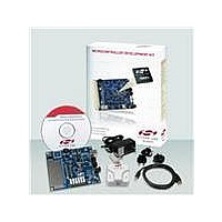
KIT DEV C8051F800
Manufacturer
Silicon Laboratories Inc
Type
MCUr
Specifications of C8051F800DK
Contents
Board, Cables, CD, Debugger, Power Supply
Processor To Be Evaluated
C8051F800
Data Bus Width
16 bit
Interface Type
USB
Operating Supply Voltage
7 V to 15 V
Lead Free Status / RoHS Status
Contains lead / RoHS non-compliant
For Use With/related Products
C8051F8xx
Lead Free Status / Rohs Status
Supplier Unconfirmed
Other names
336-1797


29.3.6. 16-Bit Pulse Width Modulator Mode
A PCA module may be operated in 16-Bit PWM mode. 16-bit PWM mode is independent of the other (8-bit
through 15-bit) PWM modes. In this mode, the 16-bit capture/compare module defines the number of PCA
clocks for the low time of the PWM signal. When the PCA counter matches the module contents, the out-
put on CEXn is asserted high; when the 16-bit counter overflows, CEXn is asserted low. 16-Bit PWM Mode
is enabled by setting the ECOMn, PWMn, and PWM16n bits in the PCA0CPMn register.
The duty cycle of the PWM output signal can be varied by writing to an “Auto-Reload” Register, which is
dual-mapped into the PCA0CPHn and PCA0CPLn register locations. The auto-reload registers are
accessed (read or written) when the bit ARSEL in PCA0PWM is set to 1. The capture/compare registers
are accessed when ARSEL is set to 0. This synchronous update feature allows software to asynchro-
nously write a new PWM high time, which will then take effect on the following PWM period.
For backwards-compatibility with the 16-bit PWM mode available on other devices, the PWM duty cycle
can also be changed without using the “Auto-Reload” register. To output a varying duty cycle without using
the “Auto-Reload” register, new value writes should be synchronized with PCA CCFn match interrupts.
Match interrupts should be enabled (ECCFn = 1 AND MATn = 1) to help synchronize the capture/compare
register writes. If the MATn bit is set to 1, the CCFn flag for the module will be set each time a 16-bit com-
parator match (rising edge) occurs. The CF flag in PCA0CN can be used to detect the overflow (falling
edge). The duty cycle for 16-Bit PWM Mode is given by Equation 29.4.
Important Note About Capture/Compare Registers: When writing a 16-bit value to the PCA0 Cap-
ture/Compare registers, the low byte should always be written first. Writing to PCA0CPLn clears the
ECOMn bit to 0; writing to PCA0CPHn sets ECOMn to 1.
Using Equation 29.4, the largest duty cycle is 100% (PCA0CPn = 0), and the smallest duty cycle is
0.0015% (PCA0CPn = 0xFFFF). A 0% duty cycle may be generated by clearing the ECOMn bit to 0.
P C A 0C P Ln
W rite to
R eset
P C A 0C P H n
W rite to
0
E N B
E N B
1
W
M
P
1
6
n
1
C
O
M
E
n
P C A 0C P M n
C
A
P
P
n
0 0 x 0
C
A
P
N
n
M
A
T
n
O
G
T
n
Equation 29.4. 16-Bit PWM Duty Cycle
Figure 29.10. PCA 16-Bit PWM Mode
W
M
P
n
Duty Cycle
E
C
C
F
n
x
P C A T im ebase
A R S E L = 1
A R S E L = 0
R /W w hen
R /W w hen
E nable
=
16-bit C om parator
(C apture/C om pare )
P C A 0C P H :Ln
P C A 0C P H :Ln
Rev. 1.0
---------------------------------------------------- -
(A uto -R eload )
P C A 0H :L
65536 PCA0CPn
–
65536
O verflow
M atch
R
A
S
E
L
S
E
C
O
V
R
P C A 0P W M
x
C
O
V
F
S E T
C LR
C8051F80x-83x
Q
Q
E
A
R
1
6
C
L
S
E
L
2
x x x
C
S
E
L
L
1
C E X n
C
S
E
L
L
0
C rossbar
P ort I/O
235
Related parts for C8051F800DK
Image
Part Number
Description
Manufacturer
Datasheet
Request
R

Part Number:
Description:
SMD/C°/SINGLE-ENDED OUTPUT SILICON OSCILLATOR
Manufacturer:
Silicon Laboratories Inc
Part Number:
Description:
Manufacturer:
Silicon Laboratories Inc
Datasheet:
Part Number:
Description:
N/A N/A/SI4010 AES KEYFOB DEMO WITH LCD RX
Manufacturer:
Silicon Laboratories Inc
Datasheet:
Part Number:
Description:
N/A N/A/SI4010 SIMPLIFIED KEY FOB DEMO WITH LED RX
Manufacturer:
Silicon Laboratories Inc
Datasheet:
Part Number:
Description:
N/A/-40 TO 85 OC/EZLINK MODULE; F930/4432 HIGH BAND (REV E/B1)
Manufacturer:
Silicon Laboratories Inc
Part Number:
Description:
EZLink Module; F930/4432 Low Band (rev e/B1)
Manufacturer:
Silicon Laboratories Inc
Part Number:
Description:
I°/4460 10 DBM RADIO TEST CARD 434 MHZ
Manufacturer:
Silicon Laboratories Inc
Part Number:
Description:
I°/4461 14 DBM RADIO TEST CARD 868 MHZ
Manufacturer:
Silicon Laboratories Inc
Part Number:
Description:
I°/4463 20 DBM RFSWITCH RADIO TEST CARD 460 MHZ
Manufacturer:
Silicon Laboratories Inc
Part Number:
Description:
I°/4463 20 DBM RADIO TEST CARD 868 MHZ
Manufacturer:
Silicon Laboratories Inc
Part Number:
Description:
I°/4463 27 DBM RADIO TEST CARD 868 MHZ
Manufacturer:
Silicon Laboratories Inc
Part Number:
Description:
I°/4463 SKYWORKS 30 DBM RADIO TEST CARD 915 MHZ
Manufacturer:
Silicon Laboratories Inc
Part Number:
Description:
N/A N/A/-40 TO 85 OC/4463 RFMD 30 DBM RADIO TEST CARD 915 MHZ
Manufacturer:
Silicon Laboratories Inc
Part Number:
Description:
I°/4463 20 DBM RADIO TEST CARD 169 MHZ
Manufacturer:
Silicon Laboratories Inc