C8051T606DK Silicon Laboratories Inc, C8051T606DK Datasheet - Page 138
C8051T606DK
Manufacturer Part Number
C8051T606DK
Description
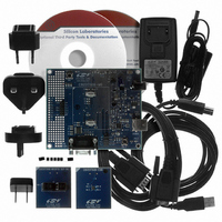
KIT DEVELOPMENT FOR C8051T606
Manufacturer
Silicon Laboratories Inc
Type
MCUr
Datasheets
1.C8051T600EDB.pdf
(188 pages)
2.C8051T606TDB.pdf
(1 pages)
3.C8051T606DK.pdf
(16 pages)
4.C8051T606TDB.pdf
(14 pages)
Specifications of C8051T606DK
Contents
Board, Adapter, Cable, CD, Power Supply
Processor To Be Evaluated
C8051T606x
Interface Type
RS-232, USB
Maximum Operating Temperature
+ 85 C
Minimum Operating Temperature
- 40 C
Operating Supply Voltage
3.3 V
Lead Free Status / RoHS Status
Lead free / RoHS Compliant
For Use With/related Products
C8051T606
Lead Free Status / Rohs Status
Lead free / RoHS Compliant
Other names
336-1666


C8051T600/1/2/3/4/5/6
24.1. Enhanced Baud Rate Generation
The UART0 baud rate is generated by Timer 1 in 8-bit auto-reload mode. The TX clock is generated by
TL1; the RX clock is generated by a copy of TL1 (shown as RX Timer in Figure 24.2), which is not user-
accessible. Both TX and RX Timer overflows are divided by two to generate the TX and RX baud rates.
The RX Timer runs when Timer 1 is enabled, and uses the same reload value (TH1). However, an
RX Timer reload is forced when a START condition is detected on the RX pin. This allows a receive to
begin any time a START is detected, independent of the TX Timer state.
Timer 1 should be configured for Mode 2, 8-bit auto-reload (see Section “25.1.3. Mode 2: 8-bit Coun-
ter/Timer with Auto-Reload” on page 149). The Timer 1 reload value should be set so that overflows will
occur at two times the desired UART baud rate frequency. Note that Timer 1 may be clocked by one of six
sources: SYSCLK, SYSCLK/4, SYSCLK/12, SYSCLK/48, the external oscillator clock/8, or an external
input T1. For any given Timer 1 clock source, the UART0 baud rate is determined by Equation 24.1-A and
Equation 24.1-B.
Where T1
value). Timer 1 clock frequency is selected as described in Section “25. Timers” on page 145. A quick ref-
erence for typical baud rates and system clock frequencies is given in Table 24.1 through Table 24.2. The
internal oscillator may still generate the system clock when the external oscillator is driving Timer 1.
138
CLK
is the frequency of the clock supplied to Timer 1 and T1H is the high byte of Timer 1 (reload
Detected
Start
A)
B)
Figure 24.2. UART0 Baud Rate Logic
UartBaudRate
T1_Overflow_Rate
Equation 24.1. UART0 Baud Rate
RX Timer
Timer 1
TH1
TL1
=
Overflow
Overflow
Rev. 1.2
1
-- -
2
=
T1_Overflow_Rate
------------------------- -
256 TH1
T1
–
CLK
2
2
UART
RX Clock
TX Clock
Related parts for C8051T606DK
Image
Part Number
Description
Manufacturer
Datasheet
Request
R

Part Number:
Description:
SMD/C°/SINGLE-ENDED OUTPUT SILICON OSCILLATOR
Manufacturer:
Silicon Laboratories Inc
Part Number:
Description:
Manufacturer:
Silicon Laboratories Inc
Datasheet:
Part Number:
Description:
N/A N/A/SI4010 AES KEYFOB DEMO WITH LCD RX
Manufacturer:
Silicon Laboratories Inc
Datasheet:
Part Number:
Description:
N/A N/A/SI4010 SIMPLIFIED KEY FOB DEMO WITH LED RX
Manufacturer:
Silicon Laboratories Inc
Datasheet:
Part Number:
Description:
N/A/-40 TO 85 OC/EZLINK MODULE; F930/4432 HIGH BAND (REV E/B1)
Manufacturer:
Silicon Laboratories Inc
Part Number:
Description:
EZLink Module; F930/4432 Low Band (rev e/B1)
Manufacturer:
Silicon Laboratories Inc
Part Number:
Description:
I°/4460 10 DBM RADIO TEST CARD 434 MHZ
Manufacturer:
Silicon Laboratories Inc
Part Number:
Description:
I°/4461 14 DBM RADIO TEST CARD 868 MHZ
Manufacturer:
Silicon Laboratories Inc
Part Number:
Description:
I°/4463 20 DBM RFSWITCH RADIO TEST CARD 460 MHZ
Manufacturer:
Silicon Laboratories Inc
Part Number:
Description:
I°/4463 20 DBM RADIO TEST CARD 868 MHZ
Manufacturer:
Silicon Laboratories Inc
Part Number:
Description:
I°/4463 27 DBM RADIO TEST CARD 868 MHZ
Manufacturer:
Silicon Laboratories Inc
Part Number:
Description:
I°/4463 SKYWORKS 30 DBM RADIO TEST CARD 915 MHZ
Manufacturer:
Silicon Laboratories Inc
Part Number:
Description:
N/A N/A/-40 TO 85 OC/4463 RFMD 30 DBM RADIO TEST CARD 915 MHZ
Manufacturer:
Silicon Laboratories Inc
Part Number:
Description:
I°/4463 20 DBM RADIO TEST CARD 169 MHZ
Manufacturer:
Silicon Laboratories Inc