DK-EMB-3C120N Altera, DK-EMB-3C120N Datasheet - Page 16
DK-EMB-3C120N
Manufacturer Part Number
DK-EMB-3C120N
Description
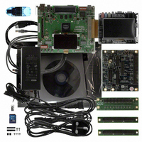
KIT DEV EMB CYCLONE III EDITION
Manufacturer
Altera
Series
Cyclone® IIIr
Type
FPGAr
Datasheets
1.DK-START-3C25N.pdf
(74 pages)
2.DK-DEV-3C120N.pdf
(48 pages)
3.DK-EMB-3C120N.pdf
(5 pages)
Specifications of DK-EMB-3C120N
Contents
Board, Cables, CD(s), USB-Blaster™, Power Supply
Architecture
PLD/FPGA
Silicon Manufacturer
Altera
Core Architecture
FPGA
Core Sub-architecture
Cyclone
Silicon Core Number
EP3C
Silicon Family Name
Cyclone III
Rohs Compliant
Yes
For Use With/related Products
EP3C120
Lead Free Status / RoHS Status
Lead free / RoHS Compliant
Other names
544-2589
Available stocks
Company
Part Number
Manufacturer
Quantity
Price
Company:

Part Number:
DK-EMB-3C120N
Manufacturer:
Altera
Quantity:
135


4–2
Powering Up the Board
Figure 4–1. Cyclone III Development Board Layout and Components
Cyclone III FPGA Development Kit User Guide
(Loopback Board Shown)
HSMC Port A (J8)
Activity LEDS (D7, D8)
Ethernet PHY TX/RX
Speaker Header (J5)
Rotary Switch (SW4)
Clock In SMA (J10)
LEDs (D1, D3, D4)
Duplex LED (D6)
Present LED (D18)
Ethernet PHY
Power Select
Ethernet PHY
HSMC Port A
Clock (Y4)
125-MHz
Switch (SW6)
User DIP
Figure 4–1
Before powering up, prepare the board by performing the following steps:
1. If cards are plugged into the high-speed mezzanine connector (HSMC) ports,
2. Ensure that the POWER switch SW2 is in the OFF (or DOWN) position.
3. Configure the 8-position SW1 DIP switch to the default settings in
Table 4–1. Switch SW1 Settings (Part 1 of 2)
Switch (SW2)
remove them
port B).
Power
Switch
User Push Buttons
1
2
(S1 through S4)
Power Display (U28)
shows the Cyclone III development board and its components.
DC Power
Jack (J2)
LED (D5)
Power
DDR2TOP_ACTIVE
(Figure
mΩ/mA
LED (D11)
Name
V/Ω
(Three on Top and Two on Bottom)
DDR2BOT_ACTIVE
DDR2 SDRAM Device Interface
Button Switch (S5)
CPU Reset Push
(U11, U12, U25, U26, U13)
4–1) shows a daughter card plugged into both port A and
LED (D16)
Four x16 and one x8
LCD (J13)
Graphics
Done LED (D25)
Configuration
Position 0
mΩ
Cyclone III FPGA (U20)
V
(D26 through D33)
User LEDs
Flash Active
Function
LED (D23)
MAX II Device
Switch (SW1)
Control DIP
MAX II CPLD (U7)
Configuration
Push Buttons
(S6 and S7)
Position 1
Reset and
Factory
mA
24-MHz Crystal (Y1)
W
Chapter 4: Development Board Setup
September 2010 Altera Corporation
User Defined
7-Segment
Display (U30)
6-MHz
Crystal (Y2)
PGM Config Select
Rotary Switch (SW5)
DIP Switch (SW3)
HSMC Port B
Present LED (D19)
Clock Out SMA (J11)
Clock (Y5)
Board-Specific LEDs
(D20 through D24)
Blaster Clock (Y3)
JTAG Control
Device Select
Jumper (J6)
50-MHz
SRAM Active
LED (D17)
24-MHz USB-
HSMC Port B (J9)
(Debug Header Shown)
Powering Up the Board
Table
Position
Default
4–1.
0
1
Related parts for DK-EMB-3C120N
Image
Part Number
Description
Manufacturer
Datasheet
Request
R

Part Number:
Description:
CYCLONE II STARTER KIT EP2C20N
Manufacturer:
Altera
Datasheet:


Part Number:
Description:
CPLD, EP610 Family, ECMOS Process, 300 Gates, 16 Macro Cells, 16 Reg., 16 User I/Os, 5V Supply, 35 Speed Grade, 24DIP
Manufacturer:
Altera Corporation
Datasheet:
Part Number:
Description:
CPLD, EP610 Family, ECMOS Process, 300 Gates, 16 Macro Cells, 16 Reg., 16 User I/Os, 5V Supply, 15 Speed Grade, 24DIP
Manufacturer:
Altera Corporation
Datasheet:
Part Number:
Description:
Manufacturer:
Altera Corporation
Datasheet:
Part Number:
Description:
CPLD, EP610 Family, ECMOS Process, 300 Gates, 16 Macro Cells, 16 Reg., 16 User I/Os, 5V Supply, 30 Speed Grade, 24DIP
Manufacturer:
Altera Corporation
Datasheet:
Part Number:
Description:
High-performance, low-power erasable programmable logic devices with 8 macrocells, 10ns
Manufacturer:
Altera Corporation
Datasheet:
Part Number:
Description:
High-performance, low-power erasable programmable logic devices with 8 macrocells, 7ns
Manufacturer:
Altera Corporation
Datasheet:
Part Number:
Description:
Classic EPLD
Manufacturer:
Altera Corporation
Datasheet:
Part Number:
Description:
High-performance, low-power erasable programmable logic devices with 8 macrocells, 10ns
Manufacturer:
Altera Corporation
Datasheet:
Part Number:
Description:
Manufacturer:
Altera Corporation
Datasheet:
Part Number:
Description:
Manufacturer:
Altera Corporation
Datasheet:
Part Number:
Description:
Manufacturer:
Altera Corporation
Datasheet:
Part Number:
Description:
CPLD, EP610 Family, ECMOS Process, 300 Gates, 16 Macro Cells, 16 Reg., 16 User I/Os, 5V Supply, 25 Speed Grade, 24DIP
Manufacturer:
Altera Corporation
Datasheet: