AT91EB42 Atmel, AT91EB42 Datasheet - Page 11
AT91EB42
Manufacturer Part Number
AT91EB42
Description
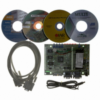
KIT EVAL FOR ARM AT91M42800A
Manufacturer
Atmel
Series
AT91SAM Smart ARMr
Type
MCUr
Datasheet
1.AT91EB42.pdf
(45 pages)
Specifications of AT91EB42
Contents
Evaluation Board, Cable, Power Jack, CD-ROM
For Use With/related Products
AT91M42800A
Lead Free Status / RoHS Status
Contains lead / RoHS non-compliant


3.1
3.2
AT91EB42 Evaluation Board User Guide
AT91EB42
Evaluation Board
Boot Software
Program
The AT91EB42 Evaluation Board embeds an AT49BV162A Flash memory device pro-
grammed with default software. Only the lowest 8 x 8 KB sectors are used. The
remaining sectors are user definable, and can be programmed using one of the Flash
downloader “Flash_16x4” solutions offered in the AT91 Library.
When delivered, the Flash memory device contains:
! the Boot Software Program
! the Functional Test Software (FTS)
! the Flash Uploader
! the power-down function
! the Angel Debug Monitor
! a default user boot with a default application (LED Swing Application)
The Boot Software Program and Functional Test Software (FTS) are in sectors 0 and 1
of the Flash. These sectors are not locked in order to provide an easy on-board
upgrade. The user must avoid overwriting these sectors.
The Boot Software Program configures the AT91M42800A, and thus controls the mem-
ory and other board components.
The Boot Software Program is started at reset if JP1 is in the STD position. If JP1 is in
the USER position, the AT91M42800A boots from address 0x01100000 in the Flash,
which must have a user-defined boot.
The Boot Software Program first initializes the master clock frequency at 32.768 MHz.
The EBI then executes the REMAP procedure and checks the state of the buttons as
described below.
! When the SW1 button is pressed:
– All the LEDs light up together.
– The D1 LED remains lit when SW1 is released.
– The Functional Test Software (FTS) is started.
The On-board Software
Rev. 1708C–ATARM–12-May-05
Section 3
3-1
Related parts for AT91EB42
Image
Part Number
Description
Manufacturer
Datasheet
Request
R

Part Number:
Description:
DEV KIT FOR AVR/AVR32
Manufacturer:
Atmel
Datasheet:

Part Number:
Description:
INTERVAL AND WIPE/WASH WIPER CONTROL IC WITH DELAY
Manufacturer:
ATMEL Corporation
Datasheet:
Part Number:
Description:
Low-Voltage Voice-Switched IC for Hands-Free Operation
Manufacturer:
ATMEL Corporation
Datasheet:
Part Number:
Description:
MONOLITHIC INTEGRATED FEATUREPHONE CIRCUIT
Manufacturer:
ATMEL Corporation
Datasheet:
Part Number:
Description:
AM-FM Receiver IC U4255BM-M
Manufacturer:
ATMEL Corporation
Datasheet:
Part Number:
Description:
Monolithic Integrated Feature Phone Circuit
Manufacturer:
ATMEL Corporation
Datasheet:
Part Number:
Description:
Multistandard Video-IF and Quasi Parallel Sound Processing
Manufacturer:
ATMEL Corporation
Datasheet:
Part Number:
Description:
High-performance EE PLD
Manufacturer:
ATMEL Corporation
Datasheet:
Part Number:
Description:
8-bit Flash Microcontroller
Manufacturer:
ATMEL Corporation
Datasheet:
Part Number:
Description:
2-Wire Serial EEPROM
Manufacturer:
ATMEL Corporation
Datasheet: