AT91EB42 Atmel, AT91EB42 Datasheet - Page 20
AT91EB42
Manufacturer Part Number
AT91EB42
Description
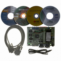
KIT EVAL FOR ARM AT91M42800A
Manufacturer
Atmel
Series
AT91SAM Smart ARMr
Type
MCUr
Datasheet
1.AT91EB42.pdf
(45 pages)
Specifications of AT91EB42
Contents
Evaluation Board, Cable, Power Jack, CD-ROM
For Use With/related Products
AT91M42800A
Lead Free Status / RoHS Status
Contains lead / RoHS non-compliant


1708C–ATARM–12-May-05
Appendix A – Configuration Straps
5.2
5-2
Configuration
Straps (CB1 - 23,
JP1 - 8)
Table 5-1. Functional Pin Assignment (Continued)
By adding the I/O and EBI expansion connectors, users can connect their own peripher-
als to the evaluation board. These peripherals may require more I/O lines than available
while the board is in its default state. Extra I/O lines can be made available by disabling
some of the on-board peripherals or features. This is done using the configuration straps
detailed below. Some of these straps present a default wire (notified by the default men-
tion) that must be cut before soldering the strap.
Note:
Note:
Pin Designation
PB17/TIOB3
PA13/MOSIA
PA12/MISOA
PA11/SPCKA
PA14/NPCSA0/NSSA
PA15/NPCSA1
PA16/NPCSA2
PA3/IRQ3
CB1
Closed
Open
CB3
Closed
Open
(1)
(1)
1. Hardwired default position: To cancel this default configuration, the user should cut
1. Hardwired default position: To cancel this default configuration, the user should cut
the wire on the board.
the wire on the board.
On-board PB5/A23/CS4 Signal
AT91 PB5/A23/CS4 signal is connected to the EBI expansion connector
(P1-B21).
AT91 PB5/A23/CS4 signal is not connected to the EBI expansion connector
(P1-B21).
This authorizes users to connect the EBI expansion connector of this board
to the MPI expansion connector of an AT91EB63 Evaluation Board without
conflicting problems.
On-board IRQ3 Signal
AT91 IRQ3 signal is connected to the external ADC (U20 pin 4).
AT91 IRQ3 signal is not connected to the external ADC (U20 pin 4). This
authorizes the user to use this signal for other applications via the I/O
Expansion connector (P2 - A8).
Function Used on the AT91EB42
General I/O input/output line to generate SDA signal dedicated for a
two wire bus access
To generate SPI bus Access to the DataFlash, EEPROM and ADC
devices
To generate SPI bus Access to the DataFlash, EEPROM and ADC
devices
To generate SPI bus Access to the DataFlash, EEPROM and ADC
devices
Chip Select signal for the SPI device: DataFlash
Chip Select signal for the SPI device: EEPROM
Chip Select signal for the SPI device: ADC
Interrupt line from the ADC device
AT91EB42 Evaluation Board User Guide
Related parts for AT91EB42
Image
Part Number
Description
Manufacturer
Datasheet
Request
R

Part Number:
Description:
DEV KIT FOR AVR/AVR32
Manufacturer:
Atmel
Datasheet:

Part Number:
Description:
INTERVAL AND WIPE/WASH WIPER CONTROL IC WITH DELAY
Manufacturer:
ATMEL Corporation
Datasheet:
Part Number:
Description:
Low-Voltage Voice-Switched IC for Hands-Free Operation
Manufacturer:
ATMEL Corporation
Datasheet:
Part Number:
Description:
MONOLITHIC INTEGRATED FEATUREPHONE CIRCUIT
Manufacturer:
ATMEL Corporation
Datasheet:
Part Number:
Description:
AM-FM Receiver IC U4255BM-M
Manufacturer:
ATMEL Corporation
Datasheet:
Part Number:
Description:
Monolithic Integrated Feature Phone Circuit
Manufacturer:
ATMEL Corporation
Datasheet:
Part Number:
Description:
Multistandard Video-IF and Quasi Parallel Sound Processing
Manufacturer:
ATMEL Corporation
Datasheet:
Part Number:
Description:
High-performance EE PLD
Manufacturer:
ATMEL Corporation
Datasheet:
Part Number:
Description:
8-bit Flash Microcontroller
Manufacturer:
ATMEL Corporation
Datasheet:
Part Number:
Description:
2-Wire Serial EEPROM
Manufacturer:
ATMEL Corporation
Datasheet: