AT91EB42 Atmel, AT91EB42 Datasheet - Page 24
AT91EB42
Manufacturer Part Number
AT91EB42
Description
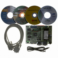
KIT EVAL FOR ARM AT91M42800A
Manufacturer
Atmel
Series
AT91SAM Smart ARMr
Type
MCUr
Datasheet
1.AT91EB42.pdf
(45 pages)
Specifications of AT91EB42
Contents
Evaluation Board, Cable, Power Jack, CD-ROM
For Use With/related Products
AT91M42800A
Lead Free Status / RoHS Status
Contains lead / RoHS non-compliant


1708C–ATARM–12-May-05
Appendix A – Configuration Straps
5-6
JP1
2 - 3
1 - 2
JP2
Open
Closed
JP3
Open
Closed
JP4
Closed
Open
JP8
2 - 3
1 - 2
User or Standard Boot Selection
The first half part of the Flash memory is accessible at its base address.
The second half part of the Flash memory is accessible at its base address.
This authorizes users to download their own application software in this part
and to boot on it.
Push Button Enabling
SW1-4 inputs to the AT91 are valid.
SW1-4 inputs to the AT91 are not valid. This authorizes users to connect the
corresponding PIO to their own resources via the I/O expansion connector.
User or Standard Boot Selection
The RS-232 transceivers are enabled.
The RS-232 transceivers are disabled. This authorizes users to connect the
corresponding PIO to their own resources via the I/O expansion connector.
PME Function (Protect Mode Enable)
The AT91M42800A is in Protect Mode.
This is the default mode on the AT91EB42. The AT91M42800A internal
registers are accessible in all processor modes.
Core Power Supply Selection
The AT91 core is powered by 3.3V power supply.
Not supported on the current microcontroller revision.
AT91EB42 Evaluation Board User Guide
Related parts for AT91EB42
Image
Part Number
Description
Manufacturer
Datasheet
Request
R

Part Number:
Description:
DEV KIT FOR AVR/AVR32
Manufacturer:
Atmel
Datasheet:

Part Number:
Description:
INTERVAL AND WIPE/WASH WIPER CONTROL IC WITH DELAY
Manufacturer:
ATMEL Corporation
Datasheet:
Part Number:
Description:
Low-Voltage Voice-Switched IC for Hands-Free Operation
Manufacturer:
ATMEL Corporation
Datasheet:
Part Number:
Description:
MONOLITHIC INTEGRATED FEATUREPHONE CIRCUIT
Manufacturer:
ATMEL Corporation
Datasheet:
Part Number:
Description:
AM-FM Receiver IC U4255BM-M
Manufacturer:
ATMEL Corporation
Datasheet:
Part Number:
Description:
Monolithic Integrated Feature Phone Circuit
Manufacturer:
ATMEL Corporation
Datasheet:
Part Number:
Description:
Multistandard Video-IF and Quasi Parallel Sound Processing
Manufacturer:
ATMEL Corporation
Datasheet:
Part Number:
Description:
High-performance EE PLD
Manufacturer:
ATMEL Corporation
Datasheet:
Part Number:
Description:
8-bit Flash Microcontroller
Manufacturer:
ATMEL Corporation
Datasheet:
Part Number:
Description:
2-Wire Serial EEPROM
Manufacturer:
ATMEL Corporation
Datasheet: